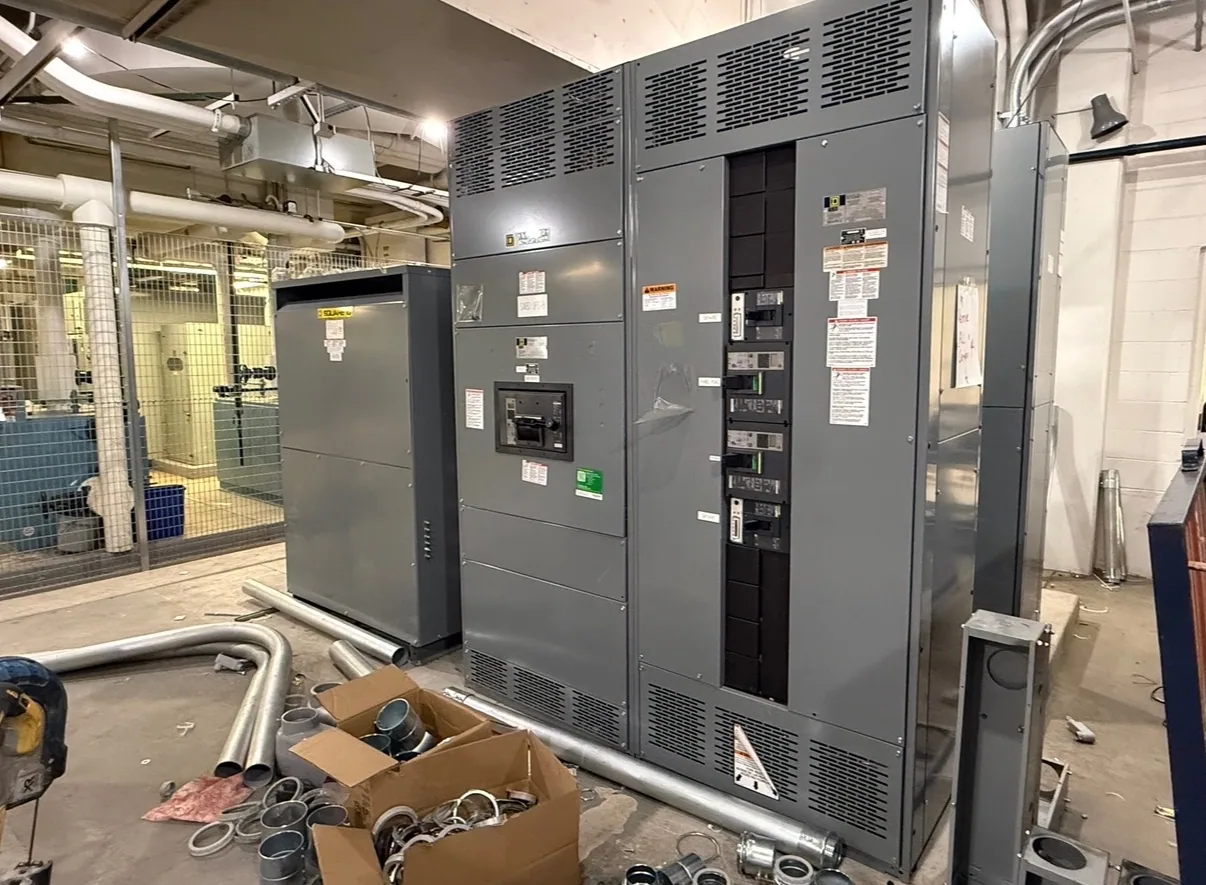
What the equipment controls
Generator paralleling equipment coordinates the connection and operation of multiple generator sources on a common electrical system. Depending on its design and specified functions, it can monitor generator conditions, determine when a source is suitable for connection, issue breaker-control commands, and coordinate operation with other sources or a utility connection. The precise scope varies by project; “paralleling” does not automatically mean every control or operating function is included.
At a conceptual level, the equipment brings sources together in a planned sequence and helps maintain the intended system arrangement. It may also support load sharing among generators and manage how available sources serve connected loads. The responsible engineer defines the operating modes, control boundaries, and required interfaces. Equipment selection should follow that design rather than an assumption that every paralleling system performs the same tasks.
Synchronization and switching
Before two AC sources are connected together, their electrical conditions must be suitable for paralleling. A specified synchronizing function may compare relevant source characteristics, such as voltage, frequency, and phase relationship, and permit or initiate a breaker-closing sequence when the required conditions are met. The acceptable settings, measurement points, and sequence depend on the system design and must be established by the responsible engineer.
Control equipment may also coordinate generator and bus breakers, including command logic, status feedback, and interlocks intended to prevent an unintended operating sequence. The exact devices and division of functions are specification-dependent: some functions may reside in relays, generator controls, or other system equipment. Confirm which component measures, decides, commands, and reports each operation, and how control power and communications are arranged.
Protection and control interfaces
Paralleling controls work alongside protective functions; they do not replace the need for a project-specific protection design. Protective relays and related devices may monitor for defined abnormal conditions and initiate an alarm, trip, or other response as specified. Which conditions are monitored, how devices coordinate, and which breaker each output affects must be determined from the system study and equipment requirements, not assumed from a general product description.
Interfaces matter as much as the controller itself. The design may involve generator-mounted controls, switchgear instrumentation, metering, remote monitoring, communications, and connections to building or supervisory systems. Specify required signals, protocols, points of control, alarm behavior, and ownership of configuration. The buyer should ask how loss of a communication link, a failed sensor, or conflicting commands are handled in the intended operating modes.
Load sharing and management
When multiple generators operate together, specified controls may coordinate real-power and reactive-power sharing. The method and accuracy depend on the generator controls, sensing, communications, and system configuration. If one unit is unavailable or a load changes, the control strategy may call for redistributing load, starting or stopping a source, or taking another defined action. Those responses are design choices, not universal features of paralleling equipment.
Load management may also include staged load addition or shedding to match available generation to demand. For example, an engineer might specify that selected noncritical loads are added in stages after a source is available, while designated loads are shed if generation capacity falls. Which loads qualify, what conditions trigger action, and how operators regain normal service require project decisions and verification against the actual equipment and operating plan.
Example and common misunderstandings
Consider a facility with two generator sources intended to support a shared bus. A project could specify that the system checks source conditions, coordinates breaker closure, shares load during parallel operation, and alarms if a defined condition occurs. If one generator is unavailable, the response might be to operate on the remaining source and limit selected loads—but only if the system design and equipment are configured for that behavior.
This example is illustrative, not a standard sequence. Paralleling equipment does not create generator capacity, guarantee uninterrupted power, or automatically determine which loads are essential. Nor does the phrase “automatic paralleling” establish the included protection, remote-control, communications, or load-shedding functions. Ask for a written operating sequence and a clear list of included controls, interfaces, and exclusions before comparing proposals.
Information to define before specifying
For a useful equipment review, provide the generator count and source information, system one-line diagram, intended operating modes, bus arrangement, and whether operation with another source is required. Identify the required loads and any planned load management, along with available generator-control data and the desired local or remote operator functions. The project engineer should establish applicable system ratings and protection requirements for the actual design.
Also identify instrumentation, communications, alarm points, control-power needs, and interfaces with external equipment. Ask which functions are included in the paralleling assembly and which are supplied or configured elsewhere. South Carolina Switchgear Builders manufactures new, custom-to-specification generator paralleling switchgear in the United States and ships nationwide. Availability and lead times depend on the order; confirm the proposed configuration, delivery timing, testing, listing, ratings, and applicable standards against the project specification before purchase.