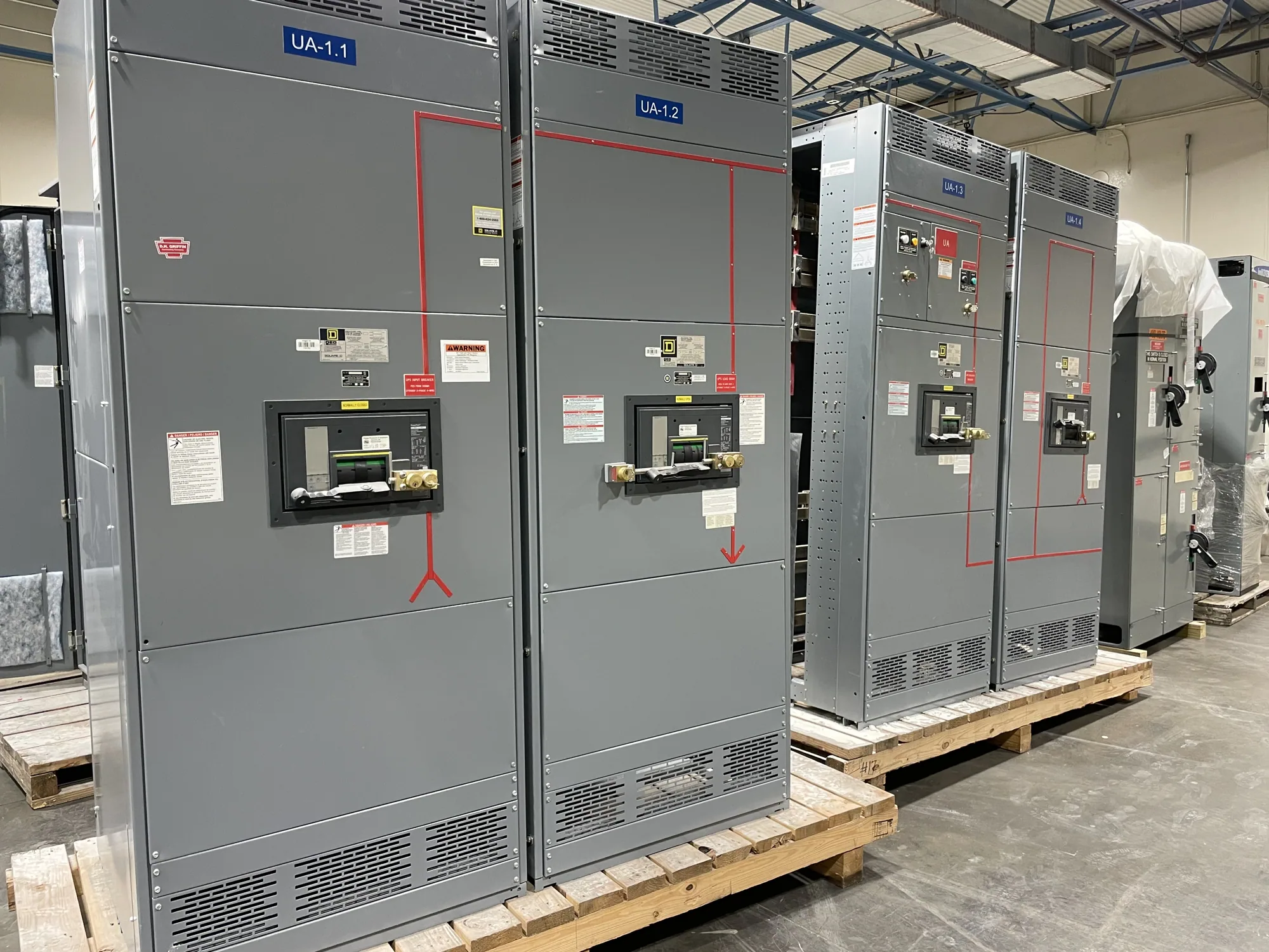
Start with the electrical system and intended use
A metal-clad switchgear lineup is described by more than its equipment name or a single voltage value. Begin with the system it will serve: identify the nominal system voltage, frequency, phase arrangement, grounding approach and whether the application is service entrance, generation, distribution or another function. State whether the lineup is intended for indoor or outdoor installation and describe its role in the one-line diagram.
These details establish context, not a complete design. A project engineer must determine which system conditions, operating scenarios and applicable requirements govern the equipment. Avoid treating a product family, voltage class or past project specification as proof that a proposed lineup is suitable for a different system. The manufacturer needs the actual project requirements to develop and review a configuration.
Describe the lineup arrangement and devices
Provide a one-line diagram and identify each lineup section and its function. List the incoming source, bus arrangement, outgoing feeders, tie or transfer functions, metering provisions and any other planned positions. For each circuit, describe the intended switching or protective device and the required operating functions. The lineup schedule should make clear how equipment is arranged and how the electrical system is expected to operate.
Clarify whether a tie is normally open or normally closed, which sources can operate in parallel, and what interlocking or control sequences the design must support. Those choices can affect protection, bus arrangements and control interfaces. Do not assume that a lineup can perform a particular sequence merely because the relevant devices appear on a drawing; have the engineer and manufacturer confirm the proposed configuration against the system design.
Specify ratings and system conditions
Identify the required continuous-current ratings and short-circuit ratings for the relevant buses and devices, along with the system fault-current information used to select them. Provide the study basis and operating assumptions where available, and ask the responsible engineer to confirm that they apply to the proposed installation. A short-circuit rating is not interchangeable with a device’s continuous-current rating, and a lineup’s rating cannot be selected from nominal voltage alone.
Also state any project-specific insulation, control-power, metering or protective-relay requirements. Ask which ratings apply to each section and device, and how the manufacturer will document the proposed design. Final ratings and available options depend on the actual equipment specification. Do not infer a rating, listing or standards compliance from a general product description; obtain confirmation for the specific lineup and its documentation.
Include physical constraints and interfaces
Useful layout information includes the equipment-room plan, access and working-space constraints, cable entry and exit directions, routing paths, and any known building or structural limits. Identify conduit, cable or bus connections and provide the interface details the design team has established. Describe environmental conditions and any project requirements that could affect enclosure selection or equipment arrangement, leaving design-specific decisions for engineering review.
Control and protection interfaces deserve equal attention. Provide the intended relay functions, control voltage requirements, metering signals, communications expectations and connections to other equipment, if specified. Clarify which party supplies external wiring, network components or associated equipment. These details help expose scope gaps early, but the responsible engineer must verify compatibility, protection coordination and the final interface design.
Use drawings and submittals to close gaps
For an initial review, assemble the one-line diagram, equipment schedule, site or room layout, project specifications and available fault-study information. Mark unresolved items instead of filling gaps with assumptions. A manufacturer can use the supplied information to identify questions and prepare project-specific submittal documents, subject to the agreed scope and confirmed design.
Review submittals for section order, device functions, nameplate data, connection locations, dimensions, control interfaces and project-specific notes. Coordinate those documents with the electrical engineer, installer and other affected trades before fabrication is authorized. A drawing review is an opportunity to resolve discrepancies, not a substitute for the engineer’s responsibility to approve the design or the installer’s responsibility to plan qualified installation and testing.
Consider an illustrative lineup and its trade-offs
Imagine a project with two incoming sources, a bus tie and several feeder circuits. Calling it “two-source switchgear” would leave important questions unanswered: whether sources may parallel, how the tie operates, which protective functions are required, what fault conditions govern the ratings and where cables enter. A one-line diagram, operating sequence and rating requirements make the intended arrangement much clearer.
More sections or control functions may support a project’s operating goals, but they also create additional interfaces and coordination decisions. Conversely, simplifying the arrangement may reduce complexity only if it still meets the engineer’s functional and protection requirements. Arc-resistant features, where considered, require separate project-specific evaluation and do not eliminate arc-flash risk. Confirm applicable design details with qualified engineering personnel and the manufacturer rather than relying on a label.
Prepare a complete project description
Before requesting a proposal, provide the system voltage and frequency, one-line diagram, lineup and device schedule, required ratings, fault-study basis, physical layout, cable and control interfaces, operating sequence, and applicable project specifications. Identify the project location, requested delivery window and any approval milestones so availability and schedule can be reviewed for the actual order. Lead times and delivery dates must be confirmed for the specific configuration.
Ask the manufacturer to identify missing inputs, state the assumptions used in its proposal and show how open questions will be resolved in the submittal process. Confirm which party owns engineering approvals, interface coordination and installation planning. A clear description gives the project team a sound basis for reviewing a new metal-clad switchgear lineup without turning preliminary information into an unverified design commitment.