The difference in one sentence
Grounding and bonding are related electrical safety functions, but they are not interchangeable. Grounding connects an electrical system or a designated conductive part to earth through the grounding system. Bonding electrically connects conductive parts so they can remain at an intended common potential and provide a low-impedance path for fault current where required.
In plain language, grounding establishes a connection to earth; bonding joins conductive components to one another. Both terms cover specific connections defined by the applicable electrical design and rules. The exact conductor, termination point, and connection method depend on the system and equipment. A general explanation cannot determine the correct arrangement for a particular installation.
What grounding is intended to do
A grounding connection relates the electrical system to earth and helps establish the system’s reference to ground. Grounding arrangements also form part of the overall response to certain electrical events, but earth itself should not be assumed to provide the normal, effective fault-current path back to the source. That path depends on the complete circuit and its bonding and grounding design.
System grounding and equipment grounding are not the same thing. System grounding concerns a connection associated with the electrical system, while equipment grounding concerns conductive equipment parts and their prescribed connection path. A project’s drawings and specifications should identify the arrangement being used rather than relying on the broad word “ground” as though it referred to one connection.
What bonding is intended to do
Bonding connects conductive parts that are required to be electrically joined. When a fault energizes a metal enclosure or another conductive part, an effective bonding path can help carry fault current through the intended circuit back toward its source, supporting operation of the applicable protective device. Whether a particular part must be bonded, and how, is determined by the system design and applicable requirements.
Bonding is not simply attaching every metal object to an earth electrode, nor does a physical connection automatically prove electrical continuity or suitability. Interfaces between equipment sections, doors, enclosures, raceways, and other components may require attention in the design. The responsible engineer and equipment documentation must establish which connections are required and how they are to be completed and verified.
Why the project design controls implementation
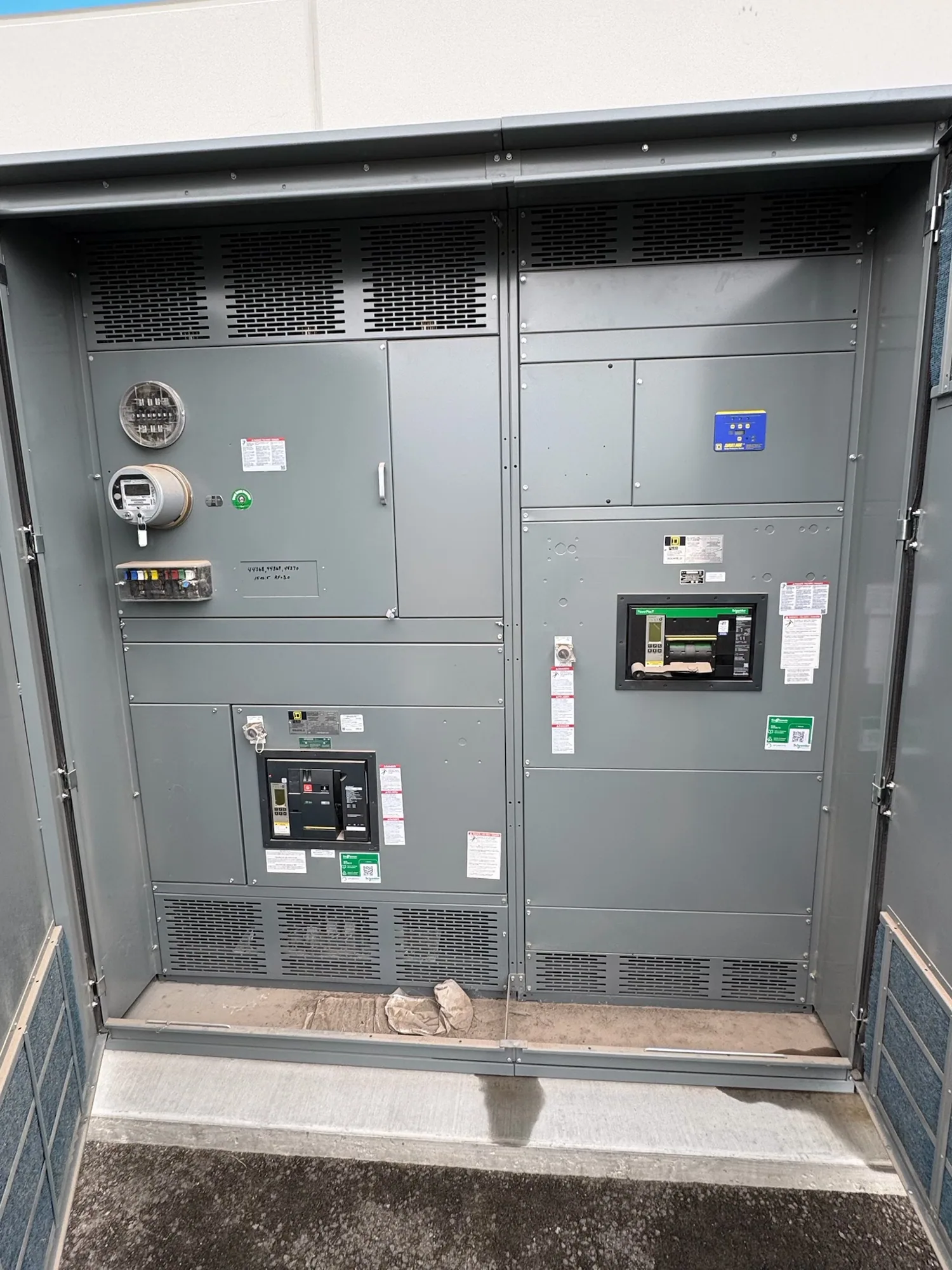
Consider a service entrance switchgear lineup with metal sections and a system neutral. Its bonding and grounding arrangement depends on the service configuration, the grounding method, the equipment design, and the installation details. A connection appropriate at one designated point may be inappropriate at another. The lineup name alone does not establish where a neutral-to-ground connection belongs.
For that reason, avoid assuming the neutral and equipment grounding conductors should be connected in every distribution assembly. The intended connection point must be determined for the actual system and shown in project documents. A designer should coordinate the one-line diagram, grounding details, equipment configuration, and installation requirements. The manufacturer can review the supplied equipment specification, but cannot replace the project engineer’s system-level decisions.
Common misunderstandings and tradeoffs
One common misconception is that grounding and bonding are synonyms because both involve conductors associated with safety. Another is that a connection to earth alone guarantees a dependable fault-clearing path. A third is that adding extra neutral-to-ground connections is always safer. These assumptions can obscure the electrical function of each connection and may conflict with the arrangement designed for the installation.
Tradeoffs are specific to the application: designers must coordinate system grounding, equipment bonding, protective devices, and the physical equipment interface without treating one connection as a substitute for another. Decisions should be checked against the adopted codes and standards, the equipment’s approved configuration, and the project’s engineering documents. Questions about a particular installation belong with the responsible qualified electrical professional.
Information to confirm before ordering equipment
When requesting distribution equipment, provide the system voltage and configuration, service or feeder role, one-line diagram, grounding method, and project specifications. Identify the intended neutral and equipment grounding connections, any required bonding interfaces, and relevant site or utility information that the project engineer has established. Include applicable codes and standards, enclosure and lineup requirements, and any project-specific listing or testing requirements for review.
Ask the manufacturer to confirm how the proposed equipment configuration addresses the documented connection points and what installation information will accompany the assembly. Do not infer a rating, listing, testing scope, or compliance solely from a product category. The project team should verify applicability for the actual design, and qualified personnel should perform installation and testing under applicable safety procedures.
Practical next step
Use the distinction as a starting point: grounding connects a designated system or part to earth; bonding joins conductive parts to establish the required electrical path. Then ask the project engineer to identify the specific grounding and bonding points on the drawings and resolve any uncertainty before equipment is finalized. For a new switchgear or switchboard order, send those documents with the equipment requirements so the proposed configuration can be reviewed against the project specification.