Suitability depends on the complete service design
Equipment is suitable for use at a service entrance when its design and documented characteristics fit the service arrangement and the requirements governing that project. The label alone does not settle the question. The responsible electrical engineer must evaluate the service configuration, system voltage, available fault current, protection, grounding and bonding, installation conditions, and applicable codes. The utility’s requirements may also affect the interface and equipment layout.
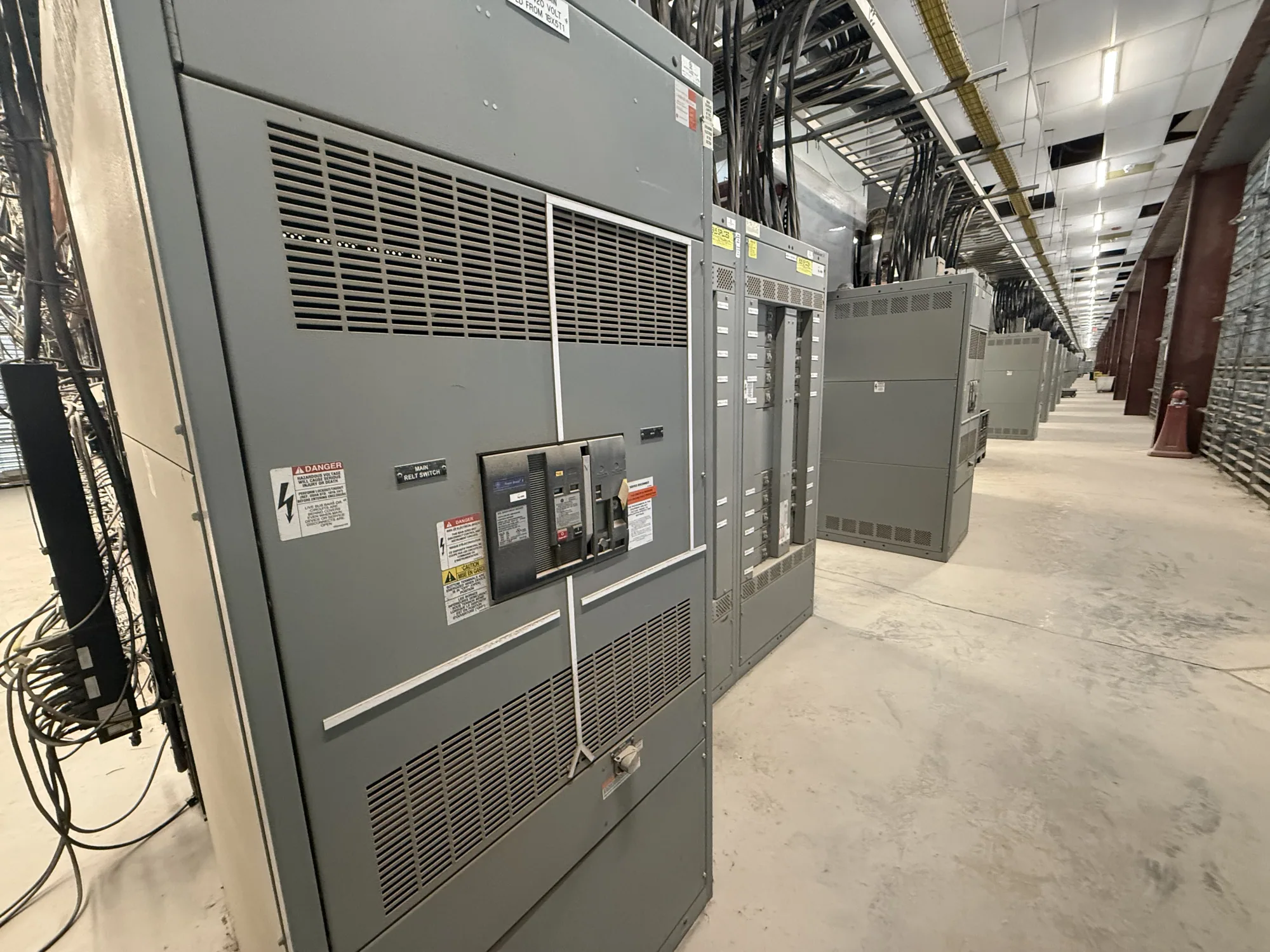
Service-entrance switchgear or a switchboard is part of a coordinated electrical system, not a standalone product designation. Two assemblies that appear similar may differ in their intended application, ratings, construction, or required markings. Confirm that the proposed equipment’s actual documentation addresses the intended use and that the complete assembly—not merely an individual component—matches the project specification.
Confirm electrical ratings and service configuration
Begin with the project’s electrical basis: nominal voltage and phase, service arrangement, frequency if specified, conductor and termination requirements, and the equipment’s required continuous-current and short-circuit ratings. The project engineer must establish the available fault current and determine what interrupting and withstand capabilities the design requires. Do not select a rating based on appearance, a previous installation, or a general description such as “service entrance rated.”
Also identify how the service will be arranged, including the number and type of incoming sources, metering provisions, main overcurrent protection, and outgoing feeders. These choices influence compartments, bus configuration, device selection, cable access, and clearances. A manufacturer can configure new equipment to specification, but the buyer should provide the engineered requirements rather than expect a generic assembly to resolve design decisions.
Read markings in context
Markings and product documentation help establish intended use, but they must be reviewed against the exact equipment and its application. Ask which markings will appear on the proposed assembly, what documentation supports them, and whether any stated listing applies to the complete assembly in the specified configuration. Listing or suitability cannot be assumed from a component’s marking or from a similar product family.
Standards and code references also require careful interpretation. Requirements depend on the equipment type, installation, jurisdiction, and adopted code edition. UL 891 is relevant to eligible low-voltage switchboards; whether it applies and whether a particular assembly is listed must be verified for that design. It should not be used to characterize medium-voltage switchgear. Have the project’s qualified engineer and the manufacturer confirm the applicable requirements and supporting documentation.
Coordinate the utility interface and grounding
Utility review is distinct from the manufacturer’s equipment design review and from approval by the authority having jurisdiction. Confirm who will obtain and document utility requirements, what information the utility needs, and whether its service rules affect metering, compartments, access, seals, incoming conductors, or other interface details. Do not treat a general equipment description as evidence of utility acceptance; requirements and decisions are project-specific.
Grounding and bonding arrangements must follow the engineered service design and applicable requirements. Clarify the intended grounding electrode connection, bonding points, neutral treatment, and any separation or connection details relevant to the equipment. These decisions depend on the actual system and installation; they are not interchangeable options to choose casually. The project engineer should define them, and the equipment drawings should reflect the approved design basis before release.
Consider installation and coordination trade-offs
For example, a project may propose a new service switchboard with a particular main device, utility metering space, and several feeder sections. If the utility later specifies a different metering interface, the lineup, compartment arrangement, or drawings may need revision. This illustrates why utility criteria should be gathered early and reconciled with the electrical design before equipment details are finalized, rather than assuming the first configuration will be accepted.
Physical constraints matter as well. Provide the equipment location, available wall and floor space, access and working-clearance requirements, cable entry direction, conductor routing, environmental conditions, and any handling or building-access limits. The engineer and installer should assess code-required clearances and installation details. A compact arrangement may reduce footprint but can constrain access or cable routing; the right trade-off must suit the site and approved design.
Prepare a useful equipment inquiry
When requesting a proposal, provide the one-line diagram, project specifications, system voltage, available fault-current information, required ratings, service and metering arrangement, grounding details, feeder schedule, and relevant utility criteria. Include drawings or site information that clarify the equipment location, dimensions, cable approach, and access constraints. Identify the project jurisdiction and the code or standard requirements already established by the design team.
Ask the manufacturer to identify assumptions, exceptions, required customer decisions, proposed equipment scope, and documentation available for review. Confirm which ratings, markings, listing status, testing, and standards apply to the offered configuration rather than relying on broad product-family language. Availability and lead time depend on the order and must be confirmed; delivery dates and configuration should be coordinated with the project schedule.
Resolve open questions before release
Before approving drawings or releasing an order, ask: Does the equipment match the engineered service configuration and fault-duty requirements? Have utility interface criteria been incorporated and reviewed by the responsible parties? Are grounding and bonding details shown clearly? Do the proposed markings and documentation correspond to the complete assembly and intended application? Are site access, clearances, cable entry, and installation constraints addressed?
Service-entrance suitability is established through that documented project review, not by a single label or a general promise of approval. The responsible engineer should resolve design and code questions, the utility should address its own interface requirements, and the manufacturer should confirm the offered equipment against the final specification. Clear answers before fabrication help align the assembly with the project’s electrical, physical, and coordination needs.