What a current transformer does
A current transformer, commonly abbreviated CT, is an instrument transformer that produces a secondary current proportional to the current flowing in its primary circuit, within the transformer’s rated conditions. The secondary signal allows compatible meters, protective relays or other instruments to sense circuit current without directly carrying the full primary current through their inputs.
In many installations, a conductor passing through the CT forms the primary, while a winding supplies the secondary signal. Other construction arrangements are possible. The device’s ratio, accuracy characteristics, burden capability and intended duty determine how that signal represents primary current. A CT is not a general-purpose power transformer, nor does it independently decide when a breaker should operate.
Why CTs matter to protection and measurement
Protective relays use CT inputs to evaluate current for functions selected by the project engineer. Depending on the design, measured current can contribute to detecting overloads, faults or other specified conditions. Relay settings and logic determine how inputs are interpreted; the CT supplies a signal and must be suitable for the intended function. Incorrect assumptions about the CT or relay interface can undermine the design.
For measurement, CT selection must also suit the meter input and the expected operating range. A ratio that is appropriate for one circuit or purpose may not provide the desired accuracy for another. Protection and metering requirements can differ, so the responsible engineer should identify the application and confirm the specified characteristics rather than choosing a CT from a ratio alone.
Application in low-voltage switchgear
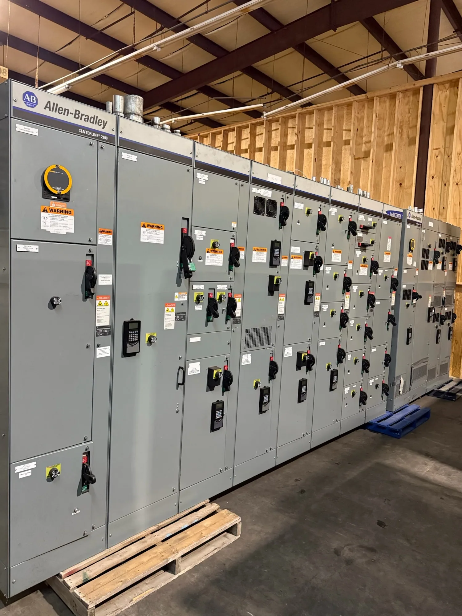
In a low-voltage switchgear or switchboard project, CTs may be associated with incoming, tie or feeder circuits, depending on the one-line diagram and monitoring or protection scheme. The equipment design must allow the CTs to fit around or connect to the relevant conductors and provide suitable secondary wiring paths to the intended devices.
Physical fit is only one part of the decision. The team should coordinate conductor arrangement, bus or cable configuration, CT mounting, access for wiring, terminal identification and the locations of meters or relays. The actual arrangement depends on the equipment design and project specification. Confirm that the switchgear manufacturer, electrical engineer and controls or protection designer are working from compatible drawings and signal requirements.
Ratio, accuracy and operating conditions
A CT ratio describes the relationship between primary and secondary current under stated conditions. For example, a hypothetical CT labeled 400:5 would be intended to produce 5 A secondary when primary current is 400 A, subject to its rating and operating characteristics. This example illustrates the ratio only; it does not establish a suitable rating, accuracy or application for any project.
Engineers also consider accuracy class, burden, frequency, thermal and mechanical requirements, and performance under fault conditions where relevant. The applicable choices depend on the connected instrument, protection function and system design. Ask the project engineer to identify the required values and confirm that the proposed CT, relay and wiring are compatible across the expected conditions.
Common misunderstandings and related terms
A CT is not interchangeable with a potential transformer, also called a voltage transformer. A CT provides a signal proportional to current; a potential transformer provides a proportional voltage signal. Both can supply inputs to instruments or relays, but they sense different electrical quantities and require distinct specifications.
Another important distinction is that CT secondary circuits have specific safety requirements. Their handling, testing and maintenance belong to qualified personnel following applicable procedures and equipment instructions. Do not treat a CT secondary as an ordinary low-voltage control circuit or assume that a relay setting can compensate for an unsuitable transformer. For protection details, consult the responsible engineer and the project’s protective relay selection criteria.
Information to confirm for a new equipment order
When planning new switchgear, provide the supplier with the current one-line diagram, circuit identification, conductor or bus arrangement, intended measurement and protection functions, and the required relay or meter inputs. Identify any project-specific CT ratios, accuracy or performance requirements supplied by the engineer. If these values are not established, request clarification before equipment configuration is finalized.
Also confirm the number and location of CTs, mounting constraints, secondary terminal and wiring expectations, and how the signals interface with protection and monitoring equipment. Ask which details are included in the equipment scope and which remain part of the field installation. Requirements, ratings, testing and applicable standards must be verified for the actual design and supplied assembly; no single CT arrangement suits every project.
Coordinate the CT with the complete system
CT selection is one part of a coordinated electrical design, not a standalone purchasing decision. The engineer should verify sensing needs, relay functions and settings, conductor geometry, equipment layout and control interfaces together. The equipment supplier can then review the specified configuration and identify information needed to prepare the new assembly. Confirm availability and delivery timing for the actual order rather than assuming a universal schedule.
Before approving drawings, reconcile the CT schedule with the one-line diagram, device data and wiring documentation. Resolve differences in ratios, terminal designations or circuit names while the design is being coordinated. This practical review helps ensure that the specified current signal, compatible protective devices and physical switchgear arrangement are treated as parts of one defined project.