Definition and scope — Equipment Grounding Conductor in Electrical Distribution
An equipment grounding conductor (EGC) is a conductor used to connect equipment and designated grounding or bonding points within an electrical system. In a distribution assembly, it may form part of the intentional conductive path associated with equipment grounding. Its purpose and connections are established by the system design and applicable requirements; the term does not identify one universal wire, color, size, or arrangement.
The EGC is distinct from the grounded circuit conductor, commonly called the neutral in applicable systems. A neutral can carry current during normal operation. An EGC is not intended to serve as a normal load-current path. How grounding and bonding connections are arranged must be determined for the actual source, service, and downstream equipment. Applicable code provisions and project documents govern, and the responsible electrical engineer should resolve design questions.
Why the distinction matters
Grounding and bonding describe related but different aspects of an electrical system. Grounding establishes connections to the system’s grounding arrangement; bonding electrically connects conductive parts where the design requires it. An EGC may participate in equipment bonding and in a fault-current path, but the term should not be confused with an electrode conductor or treated as a catch-all label for every grounding connection.
Keeping the neutral and equipment grounding functions distinct helps prevent ambiguity in drawings and equipment schedules. Whether, and where, a neutral-to-enclosure bond is specified depends on the system configuration and location in the distribution arrangement. It should not be assumed that every switchboard section, panel, or downstream assembly requires the same connection. Confirm the intended neutral treatment and bonding points with the responsible engineer.
Application in a switchboard project
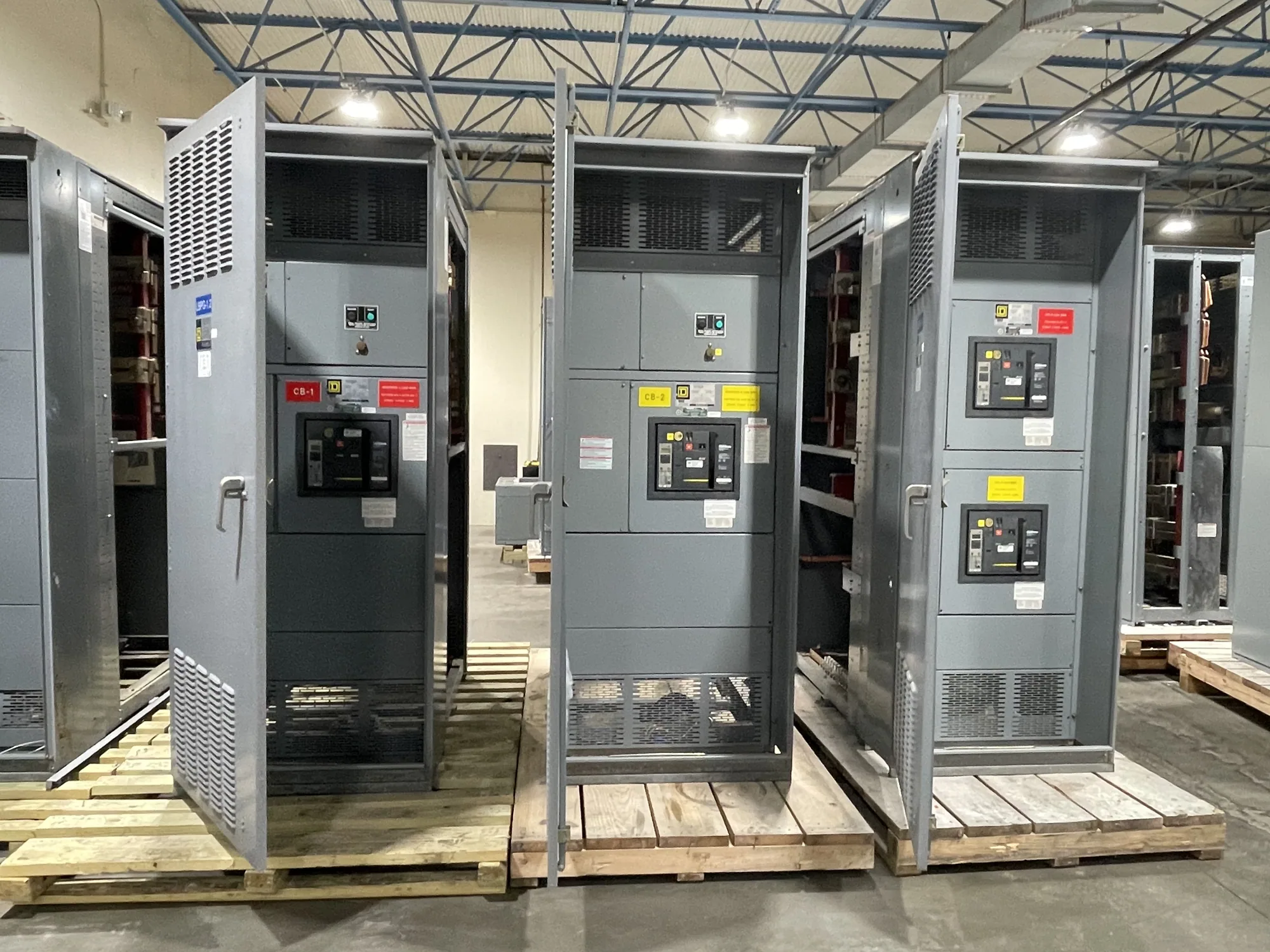
Consider a conceptual new low-voltage switchboard project. The project documents identify the source arrangement, incoming conductors, neutral requirements if applicable, and the intended grounding and bonding connections. The equipment supplier can then review the specified provisions for the assembly, such as the grounding bar or connection points, against the approved design. This example assumes no particular voltage, fault rating, service configuration, or code outcome.
That review is not a substitute for system design. The engineer establishes the required electrical characteristics and connection scheme; the manufacturer configures the new equipment to the confirmed specification. For a switchboard, ask how the grounding provision is represented in the drawings and what field connections are expected. Any listing, rating, test, or standard applicability must be confirmed for the specific assembly rather than inferred from the glossary term.
Common interpretation errors
A frequent mistake is treating the EGC as interchangeable with the neutral because both may appear in the same equipment. They have different functions, and a design should identify them separately. Another mistake is assuming a metal enclosure automatically answers every grounding question. The enclosure, internal bonding path, grounding bar, and field conductors must be considered as part of the specified assembly and installation.
Also avoid assuming that the word “ground” alone describes a complete design. The source and system arrangement affect how grounding and bonding points are established. A grounding electrode conductor, a grounded conductor, and an equipment grounding conductor are related vocabulary, not synonyms. Where drawings use unclear labels or omit connection details, request clarification before equipment configuration or installation proceeds.
Information to confirm before ordering
For a new switchboard or other distribution assembly, provide the supplier with the project’s current one-line diagram, applicable equipment schedule, and written electrical specification. Identify the system voltage and arrangement, the intended neutral configuration, and the required grounding and bonding provisions. Include any relevant incoming and outgoing connection details, project-specific standards, and documentation requirements established by the design team.
Ask the responsible engineer to confirm which components are expected to be bonded, where the EGC terminates, and whether the neutral is isolated or bonded at the particular point in the system. Clarify who supplies conductors and makes field connections, and how those details will appear on approved drawings. These questions help align the design documents, equipment configuration, and installation scope without asking the supplier to make unstated engineering assumptions.
Coordinate design, equipment, and installation
Grounding and bonding decisions should be settled early enough to be reflected in the equipment specification and reviewed drawings. If the project changes its source arrangement, neutral requirements, or distribution layout, revisit the grounding notes rather than carrying forward assumptions from an earlier design. Confirm equipment availability and delivery timing against the actual order; configuration and schedule depend on the approved specification.
Installation, inspection, testing, and maintenance belong to qualified personnel following the applicable project procedures and safety requirements. The glossary definition can help teams use the term consistently, but it does not replace the project’s engineering documents or governing requirements. A clear sequence—engineer defines the arrangement, supplier confirms the equipment configuration, and qualified personnel install it—helps keep responsibilities and connection details explicit.