What “main disconnect” means
A main disconnect is a device, or coordinated arrangement of devices, intended to disconnect a defined electrical supply or section of equipment from its source. The word “main” describes its role within a particular system boundary; it does not by itself identify a universal location, device type, rating, or code requirement. The drawings and equipment documentation should make clear exactly what is being disconnected.
In a distribution assembly, the main disconnect may be associated with the incoming supply and may separate downstream equipment from that supply. The arrangement could involve a circuit breaker, a switch, or another specified device, depending on the design. Whether it provides overcurrent protection, how it is operated, and what conductors or sections it controls must be determined from the actual equipment design and applicable project requirements.
Define the boundary before selecting equipment
The most important question is not simply “Where is the main?” but “What does this device disconnect?” A building service, a switchboard, a switchgear lineup, a particular bus section, or a downstream load may each have a distinct disconnecting boundary. A one-line diagram should show the source, the disconnecting device, and the equipment or circuit on its load side, with naming consistent across drawings and specifications.
For example, consider a conceptual low-voltage distribution project with one incoming source feeding an assembly and several outgoing circuits. The project team might designate the incoming device as the main disconnect for that assembly. That description is only meaningful once the drawings identify the source and the assembly boundary. It does not establish a particular voltage, current rating, fault duty, device technology, or code interpretation; those details belong to the project specification and engineering review.
Connection to low-voltage switchgear
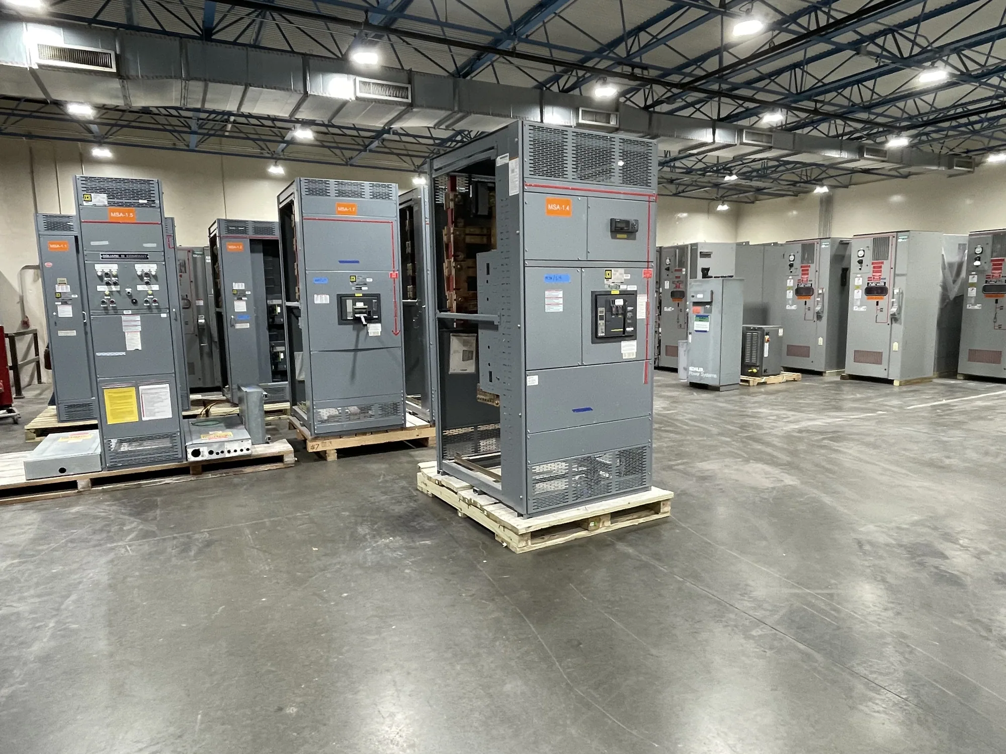
In a low-voltage switchgear project, the main disconnect is one part of a coordinated equipment design, not a synonym for the entire lineup. The engineer and manufacturer need to align the incoming arrangement with the specified source, bus configuration, outgoing devices, metering or control needs, and available space. Decisions about isolation, protection, and operation can affect the assembly layout and how its sections relate to one another.
Switchboards and switchgear are related distribution equipment terms, but they are not interchangeable labels for every assembly. UL 891 applies to eligible low-voltage switchboards; applicability and any assembly listing must be verified for the specific design. Do not assume that a phrase such as “main disconnect” establishes a product category or a listing. Standards, code provisions, utility rules, and authority having jurisdiction requirements must be reviewed for the actual installation and equipment.
Common misunderstandings and tradeoffs
A main disconnect is not automatically the same thing as the service disconnect, an emergency disconnect, a feeder disconnect, or an individual branch-circuit breaker. Those terms describe different functions or boundaries in particular contexts. A device can serve more than one role only if the project design and applicable requirements support that interpretation. Clear labels and coordinated drawings help prevent a device from being mistaken for a disconnect that controls a larger or different portion of the system.
Design tradeoffs may include how the incoming device is arranged, how much equipment it controls, how the assembly is divided, and how operators identify the relevant boundary. A more detailed division of equipment may support distinct operating zones, but can also affect layout, coordination, and specification complexity. These are project-specific engineering decisions. The responsible engineer should evaluate system conditions and applicable requirements rather than relying on the glossary term alone.
Information to confirm with the project team
Before requesting new equipment, provide the current one-line diagram and identify the intended source and load-side boundary of each disconnect. Share the project voltage class, system arrangement, available fault information, required protective functions, and any stated equipment ratings, as established by the responsible engineer. Also identify the installation context, operating needs, metering or control requirements, and the project documents that govern applicable codes and standards.
- Which supply or equipment section must the main disconnect isolate?
- Is the device intended to provide overcurrent protection, or only a disconnecting function?
- What device type, operating method, and coordination requirements does the design specify?
- Which code, utility, and authority having jurisdiction requirements apply to this installation?
- What labels, drawings, and equipment boundaries must remain consistent?
From definition to equipment specification
A glossary definition helps the team use a term consistently, but it is not a complete procurement specification. Translate the intended disconnecting boundary into the one-line diagram, equipment schedule, and written requirements. Ask the engineer to resolve any ambiguity about the device’s function or scope before the manufacturer develops a configuration. Confirm project-specific ratings, availability, standards applicability, and delivery expectations against the final requirements; availability and lead times depend on the order.
South Carolina Switchgear Builders manufactures new equipment to specification, including low-voltage distribution equipment, and ships nationwide. For a project inquiry, share the relevant design documents and explain what the main disconnect must control. Qualified personnel are responsible for installation, testing, and maintenance under applicable safety procedures. With a clearly defined boundary and coordinated documentation, the term can guide equipment selection without substituting for engineering review.