What a one-line diagram represents
A one-line diagram is a simplified representation of an electrical power system. It uses symbols and connecting lines to show how sources, distribution equipment, and loads relate to one another. Rather than drawing every conductor separately, the diagram commonly represents a circuit or group of conductors with one line. The drawing’s purpose is to make the system arrangement easier to understand, not to portray every physical detail.
Depending on its scope, a diagram may identify incoming power, transformers, bus sections, protective devices, feeders, and major loads. Labels and notes can identify equipment types or electrical characteristics, but the details shown vary by project. The responsible electrical engineer establishes what information belongs on the drawing and confirms that it agrees with the project documents and actual design.
Why the drawing matters to equipment planning
For a new low-voltage switchgear project, the one-line diagram gives the equipment manufacturer and project team an overview of how the proposed assembly fits into the distribution system. It can clarify the intended number and arrangement of sources, sections, and outgoing circuits. That context helps expose questions early, such as whether a design includes a main device, multiple incoming sources, or a bus connection that needs further coordination.
The diagram is a planning and communication document, not a complete equipment specification. It may not define enclosure details, access requirements, dimensions, environmental conditions, control wiring, or every device selection. Buyers should provide the current diagram along with the written specification and project requirements. The manufacturer can then review the requested equipment configuration against the information supplied and identify items that require clarification.
Codes, standards, and project responsibility
A one-line diagram does not, by itself, demonstrate that an installation or equipment assembly complies with applicable requirements. Codes, product standards, utility rules, and authority having jurisdiction expectations may affect the project, but their applicability depends on the location, system, equipment, and scope. The project engineer and other responsible parties should determine which requirements govern and document them in the design and procurement package.
For eligible low-voltage switchboards, UL 891 may be relevant; applicability and any assembly listing must be verified for the specific design. Do not assume a diagram proves listing, testing, or compliance, or that a requirement for one equipment type applies to every switchgear product. Confirm the requested standards and documentation with the responsible engineer and manufacturer before an order is finalized. Equipment ratings and options also need confirmation against the actual specification.
Reading a conceptual example without overreaching
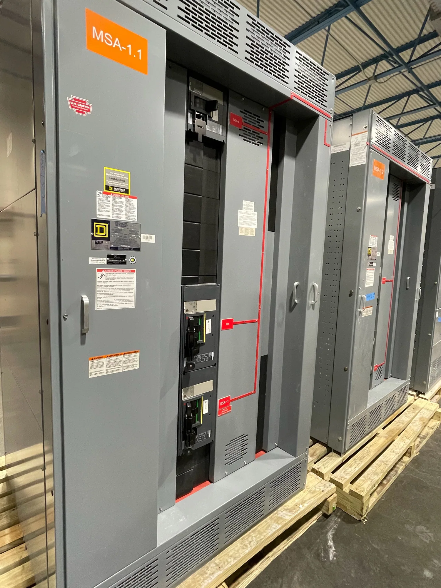
Consider an illustrative project in which a drawing shows an incoming source feeding a low-voltage switchgear assembly, with outgoing feeders serving several building loads. This describes a basic relationship: source, distribution point, and downstream circuits. It does not establish a voltage, current rating, interrupting capability, device setting, physical layout, or whether the equipment is suitable for a particular installation. Those details must come from the approved design and project specification.
A frequent misinterpretation is treating a one-line as a wiring diagram or construction drawing. Its simplified symbols may omit conductor routing, terminal details, and control connections. Another is assuming that every item drawn is included in a manufacturer’s scope; responsibility boundaries should be explicitly stated. If revisions change sources, loads, or circuit arrangement, the project team should coordinate the updated drawing with procurement and related documents.
Information to share when requesting new equipment
When requesting a proposal, provide the latest one-line diagram and identify its revision or status. Include the equipment type and voltage class, required configuration, project specification, applicable documents, and known site constraints. If the project has defined ratings, operating conditions, or interface requirements, include them as engineer-approved information rather than relying on the drawing alone. Mark open decisions clearly so that assumptions are not mistaken for confirmed requirements.
Ask the supplier which details remain unresolved, what equipment is included, and what submittals or drawing reviews are part of the project. Confirm whether proposed changes require the engineer’s approval and how revisions will be managed. Availability and actual lead times depend on the order and must be confirmed. New equipment can be custom to specification; final configuration, ratings, delivery timing, and applicable listing details require review of the specific order.
Use the diagram as a starting point
Before procurement, have the responsible engineer check that the diagram reflects the intended system and coordinates with the specifications and other project documents. Ask whether source and feeder relationships are clear, whether equipment boundaries are defined, and whether the drawing is current enough for quotation or release. These checks help the buyer and manufacturer discuss the same design basis without treating an incomplete drawing as final approval.
A one-line diagram is most useful when read as a concise map of electrical relationships: it shows what connects to what, while the full project documents establish how the equipment must be designed and delivered. For a new switchgear or switchboard order, use it to frame questions, resolve scope, and support engineering review. Qualified personnel must handle installation, testing, and maintenance under applicable safety procedures.