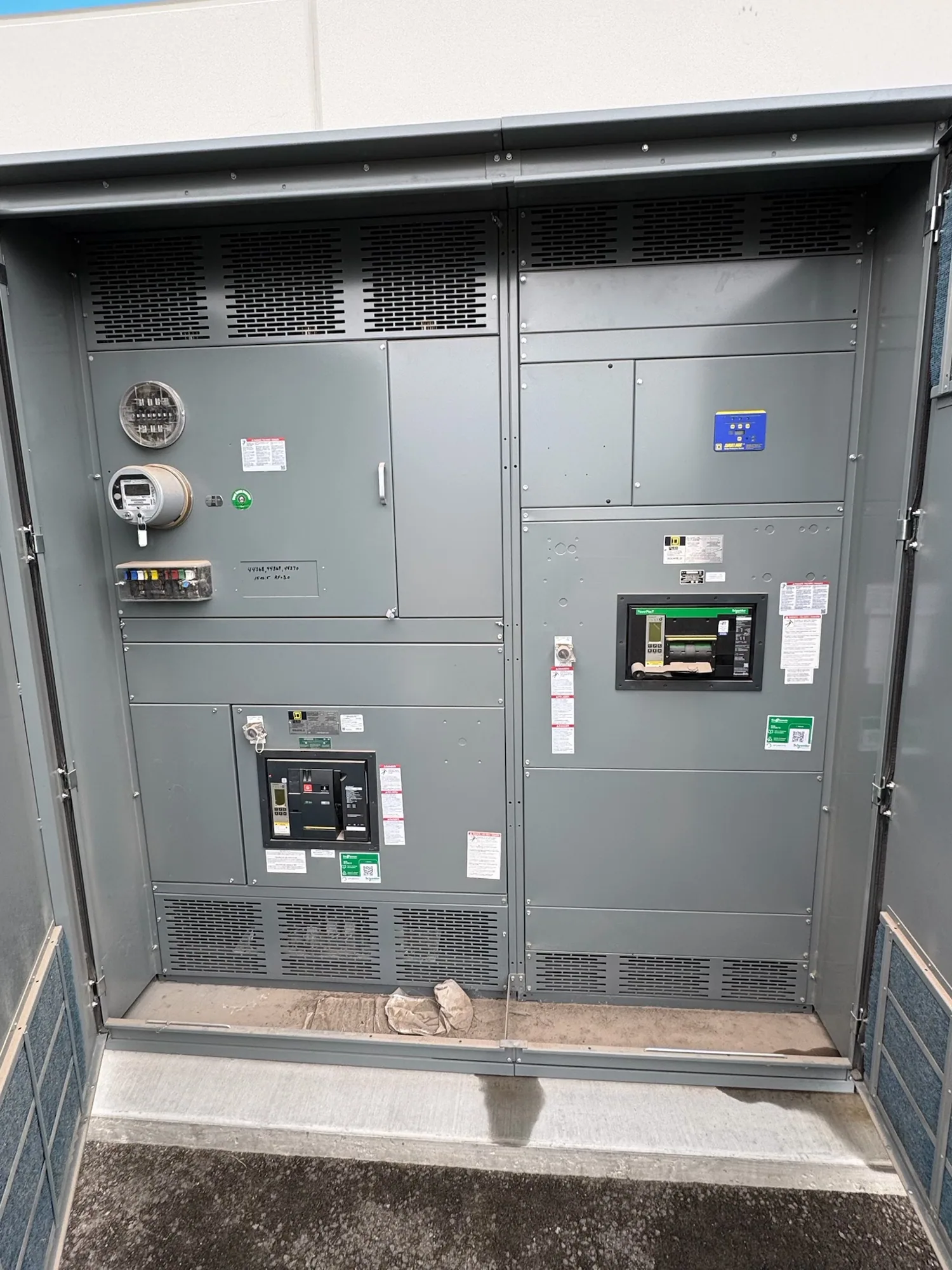
What generator paralleling means
Generator paralleling is the engineered process of connecting two or more generator sources to a common electrical system so they can operate together. The generators must be coordinated through control and switching equipment; simply connecting their outputs does not establish a safe or functional parallel arrangement. The design defines when a source may connect, how sources share operation, and how the system responds to changing conditions.
The term describes a system function, not a single product or a universal one-line configuration. A project may use dedicated paralleling switchgear, a switchboard with specified control and switching provisions, or other equipment selected by the responsible engineer. Which arrangement applies depends on the generator package, distribution architecture, load requirements, and applicable project criteria. Equipment capabilities and ratings must be verified against the actual design.
How sources are coordinated
Before a generator is connected to an energized bus, the controls and protective scheme must establish that the source is suitable to connect under the engineered sequence. That sequence may address synchronization, switching permissives, protective functions, and the transition between operating states. The specific functions and settings are project-dependent; they should be defined by the engineer and coordinated with the generator supplier and equipment manufacturer.
After connection, the system may coordinate generator loading and respond to a source becoming unavailable or a load changing. The intended behavior could differ between standby, emergency, and other operating arrangements. Do not assume that every paralleling system provides the same load-sharing method, redundancy, transfer behavior, or operating modes. Those expectations belong in the project requirements and should be checked against the proposed controls and equipment.
Metering, status, and communications
Metering and status points help operators and supervisory systems understand what the distribution equipment is doing. A project team should identify which electrical measurements, breaker states, alarms, and operating conditions need to be available locally or communicated elsewhere. The required points depend on operating procedures and the monitoring system; including a communications interface does not, by itself, determine what data is exposed or how it is used.
When instrumentation or communications are required, specify the intended interface, protocol, network boundary, and responsible system integrator. Clarify which device supplies each point, which party configures it, and how access is controlled. Cybersecurity expectations should be addressed with the project’s IT or controls stakeholders, including separation from other networks where required. These details are useful early because they can affect component selection, panel space, wiring, documentation, and acceptance planning.
Relationship to service-entrance equipment
Generator paralleling and service-entrance switchgear address related but distinct parts of an electrical distribution design. Service-entrance equipment is associated with the incoming utility supply and its distribution functions; paralleling equipment coordinates generator sources and their connection to a system. A project may require both functions, but that does not mean one assembly automatically performs every function or that its configuration is interchangeable with another.
For a conceptual example, assume a facility is evaluating a new service-entrance arrangement and wants generator operation during a utility interruption. The design team would determine where the generator connection belongs, what sources may operate together, and how switching and protection coordinate with the incoming supply. These are assumptions for discussion, not a prescribed topology. The responsible engineer must establish the actual sequence and confirm equipment suitability against the project specification.
Common misunderstandings and trade-offs
Paralleling does not simply mean that multiple generators are installed at the same site. They must be designed to operate together through a defined control and protection scheme. Nor does the term specify a particular voltage class, equipment rating, protocol, or standard. Those characteristics are separate design decisions. Avoid treating a general glossary definition as a substitute for a project one-line diagram, sequence of operations, or equipment specification.
Design trade-offs may include how much operating flexibility is needed, how the system should respond to a source or component being unavailable, and how much monitoring is useful. More points and interfaces can support visibility but also require clear ownership of integration, configuration, and testing. The project team should balance operational needs with complexity and confirm which functions belong in the generator controls, switchgear, switchboard, or supervisory system.
Information to establish before specifying equipment
For a new equipment quotation, provide the one-line diagram, generator information, intended operating modes, and the sequence the system must follow. Identify the incoming-source arrangement, loads to be served, desired metering and status points, communications requirements, and any project-specific protective functions. Include applicable drawings and specifications, plus the parties responsible for generator controls, network integration, and field installation.
Ask the engineer and supplier to identify assumptions, interface boundaries, required ratings, and items that remain to be confirmed. Discuss enclosure and installation constraints, documentation expectations, coordination with other equipment, and the planned review and acceptance process. Availability and actual lead times depend on the order and must be confirmed. For manufacturer-supplied new switchgear or switchboards, a clear functional specification helps align the proposed assembly with the project without assuming an unverified configuration.
Related terminology and next steps
Terms such as synchronization, protective relaying, instrumentation, and motor starter describe other elements that may appear in a distribution or controls discussion; they are not synonyms for generator paralleling. A process-oriented specification should spell out interfaces and required functions rather than relying on the glossary term alone. Review the project’s instrumentation and communications needs with the engineer, and coordinate any service-entrance equipment requirements within the same system design.
Use the definition as a starting point: identify the sources, connection point, operating sequence, protection, and information operators need. Then have qualified project professionals resolve the detailed design and equipment requirements. This gives the equipment manufacturer a clearer basis for proposing a new assembly and gives the project team a practical way to check whether the specified functions, interfaces, and responsibilities fit together.