What “main bus” means
A main bus is the primary bus system within electrical equipment that carries power from an incoming source and supplies portions of the lineup. It consists of connected conductors arranged to distribute current to downstream sections or devices. In a switchgear lineup, the main bus is a central distribution path; it is distinct from an individual feeder conductor, a neutral bus, or a grounding bus.
The term describes a function and location within an assembly, not a complete equipment rating or a universal physical layout. A project specification must still define how the bus connects to the incoming equipment, which sections it serves, and how the assembly is arranged. The meaning can vary in casual conversation, so engineers and suppliers should use drawings and defined terms when communicating design details.
Where it fits in low-voltage switchgear
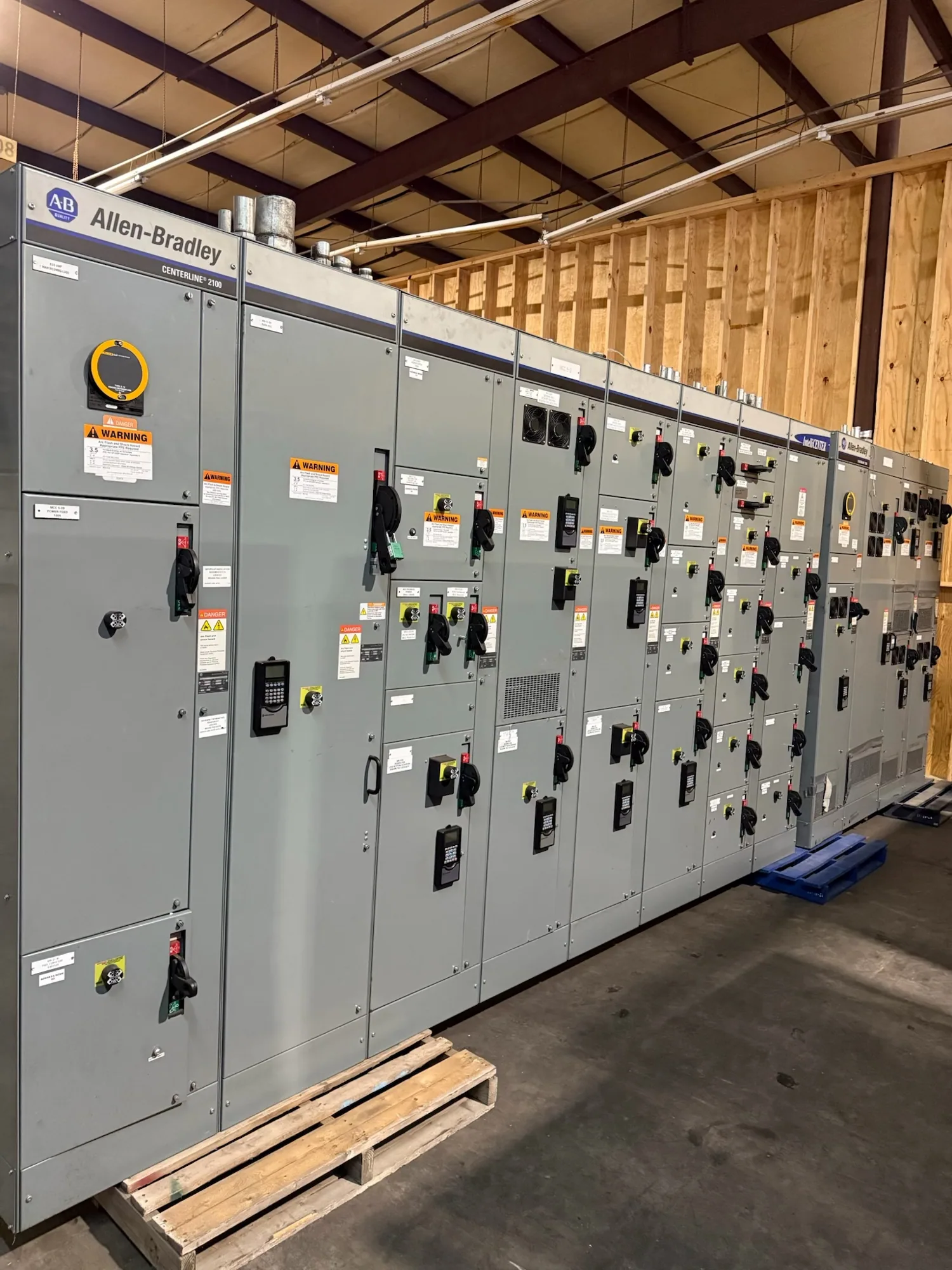
In low-voltage switchgear, the main bus typically distributes incoming power along the lineup to sections that contain switching and protective devices. The path may be arranged horizontally, vertically, or through a combination defined by the assembly design. Equipment configuration, source arrangement, section count, and the intended connections all influence how the main bus is implemented.
Calling a bus the “main” bus does not establish its voltage, current capacity, short-circuit withstand, material, or temperature limits. Those are project-specific requirements that must be coordinated with the responsible engineer and verified for the proposed assembly. Low-voltage switchgear is not interchangeable with medium-voltage switchgear, and product descriptions should preserve the voltage class specified for the project.
Busbar design: practical considerations
Busbar material and cross-section affect electrical resistance, heat generation, mechanical strength, and how conductors fit within the equipment. A larger cross-section may help address electrical or thermal demands, but it also affects space, weight, supports, and connection geometry. The responsible design team must evaluate the complete arrangement rather than selecting bus dimensions from a rule of thumb or a single nameplate value.
Bracing and support spacing matter because fault-current forces can impose mechanical stress on conductors and joints. Temperature rise depends on the bus design and assembly conditions, including enclosure and ventilation characteristics where applicable. Joint design, surface preparation, fastening method, and access for inspection also deserve attention. If conductors or sections experience thermal expansion, the design should account for movement without compromising connections or support.
Conceptual example: supplying multiple sections
Consider a hypothetical low-voltage lineup with an incoming section and several downstream sections. The main bus is the shared distribution path that supplies those sections; individual feeder devices connect loads or other equipment to the bus. This example explains the vocabulary only. It does not assume a voltage, current rating, fault duty, conductor material, or particular bus arrangement, all of which require project-specific confirmation.
A common misunderstanding is to use “main bus” and “main breaker” as though they were the same component. The bus is the conductor system; a breaker is a switching and protective device that may connect to or protect part of that system. Another is to assume that every conductor called a bus has the same role. A neutral bus serves neutral connections, while a grounding bus serves equipment grounding connections; these functions should not be conflated.
Questions to resolve before specifying equipment
- What source and incoming-device arrangement will supply the lineup, and which sections must the main bus serve?
- What project electrical requirements, including applicable current and fault-duty information, should govern the design?
- Does the specification require a particular bus material, configuration, joint approach, or future extension provision?
- How should neutral and grounding conductors be arranged, and are separate or special provisions needed?
- Which drawings, connection details, dimensions, and equipment interfaces must be coordinated with adjacent systems?
These questions help the equipment supplier understand the intended application without treating an isolated busbar dimension as a complete design. The project engineer should confirm requirements and resolve any conflicts among the one-line diagram, equipment specification, layout, and connection information before the assembly is finalized.
From definition to a project-ready specification
For a new switchgear order, provide the one-line diagram, equipment voltage class, lineup layout, incoming and outgoing connection requirements, and applicable project specifications. Identify the intended main-bus function and any constraints on material, section arrangement, access, or future connections. The supplier can then review the requested configuration and confirm which details are feasible for the specific design.
South Carolina Switchgear Builders manufactures new equipment to specification, including low-voltage switchgear, and ships nationwide. Availability and lead times depend on the order and should be confirmed. Any requested ratings, testing, listing, or standards applicability must likewise be checked against the actual assembly. A clear definition of the main bus is a useful starting point; coordinated project documents turn that definition into equipment requirements that can be reviewed and confirmed.