Definition and scope — Selective Coordination in Electrical Distribution
Selective coordination is the selection and, where applicable, adjustment of overcurrent protective devices so that an overcurrent event is interrupted by the device closest to its source, while upstream devices remain closed when the defined coordination criteria are satisfied. The practical goal is to limit the portion of an electrical system taken out of service. The term describes a protective-device relationship, not a particular switchgear product or a guarantee that every fault will affect only one circuit.
Coordination depends on the system configuration, available fault current, device characteristics, settings, and the criteria adopted for the project. Applicable codes, standards, and owner requirements may define where coordination is required and how it is evaluated. The responsible electrical engineer must identify those requirements for the actual installation. A glossary definition cannot establish compliance, prove a design, or substitute for a project-specific study.
How protective-device timing works
Overcurrent devices respond according to their operating characteristics. A downstream breaker or fuse is intended to clear a fault on its branch circuit before an upstream device operates. Coordination analysis compares the devices’ time-current behavior across the relevant current range. If their operating regions overlap, both devices may respond to some events; if separation is maintained over the required range, the design can better support selective interruption.
Time is only one part of the evaluation. Device type, trip-unit functions, pickup values, intentional delays, tolerances, and the magnitude of available fault current can change the relationship. A setting that improves separation at one current may affect protection or coordination elsewhere. Device manufacturers’ data and the exact proposed configurations matter; generic curves or assumed settings should not be treated as proof for a specific assembly.
Why it matters in low-voltage switchgear
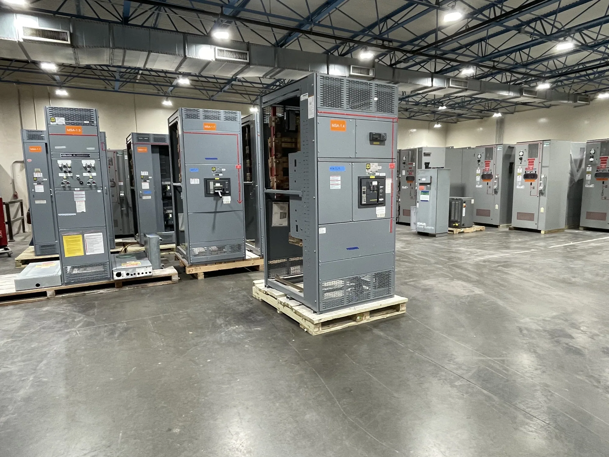
In a low-voltage switchgear project, a main protective device may feed distribution sections, downstream switchboards, panelboards, or equipment loads. A fault on one outgoing circuit can have consequences beyond that circuit if an upstream device also opens. Selective coordination is therefore considered alongside system protection, continuity needs, equipment capabilities, and the project’s required operating conditions.
For example, assume a facility has a main device feeding a distribution section and a smaller downstream device serving one branch. If a fault occurs on that branch, the design objective may be for the branch device to interrupt it while the main remains closed. That outcome is not automatic: the engineer must assess the fault-current range, device data, settings, and applicable criteria. This conceptual example supplies no ratings and does not predict performance for a real installation.
Trade-offs and common misunderstandings
Coordination is not simply a matter of making every upstream device slower. Delays can influence how long equipment is exposed to fault current and may affect other protection objectives. The engineer must balance selective operation with equipment protection, system stability, and any applicable limits. The right choice depends on the complete design; there is no universal setting or device combination that works for every distribution system.
Selective coordination is also distinct from selective tripping as an assured outcome under all possible faults. Depending on the devices and the fault level, their characteristics may not remain separated throughout every operating region. Nor does a coordinated design mean that a fault is harmless, or that equipment can be operated or serviced without required safety procedures. Arc-flash analysis addresses related but separate questions about incident energy and protective boundaries; coordination alone does not determine arc-flash risk.
Information needed for a project evaluation
Before specifying new switchgear, provide the responsible engineer and equipment supplier with the one-line diagram, system voltage, source and transformer information, anticipated loads, and downstream device schedule. Include available fault-current information when established, existing or proposed protective-device manufacturer and model data, trip-unit functions, and any required settings. Identify which loads or system portions must remain energized after a defined fault, and state the project’s coordination criteria.
Also clarify the scope of the requested equipment: voltage class, lineup arrangement, incoming and outgoing connections, space constraints, and interfaces with downstream distribution. Ask which devices and operating modes are included in the coordination evaluation, what information remains to be confirmed, and who is responsible for final settings and documentation. Availability, configuration, ratings, testing, and applicable listing details must be checked against the actual specification and equipment; none should be assumed from the term alone.
From definition to specification
This glossary entry explains the meaning of selective coordination. Applying it to a project requires a documented engineering process: establish the system conditions and criteria, evaluate protective-device characteristics, resolve conflicts, and communicate final settings and assumptions to the parties responsible for the installation. When comparing equipment proposals, confirm that the specified devices and configurations match the basis used for that evaluation.
For a new low-voltage switchgear order, provide the project requirements early so the proposed design can be reviewed against the intended system and coordination approach. Ask the engineer to identify any remaining decisions, and have qualified personnel perform installation, testing, and maintenance under applicable safety procedures. Clear coordination between design, equipment selection, and project execution helps turn the term into a practical, verifiable requirement rather than an ambiguous line in a specification.