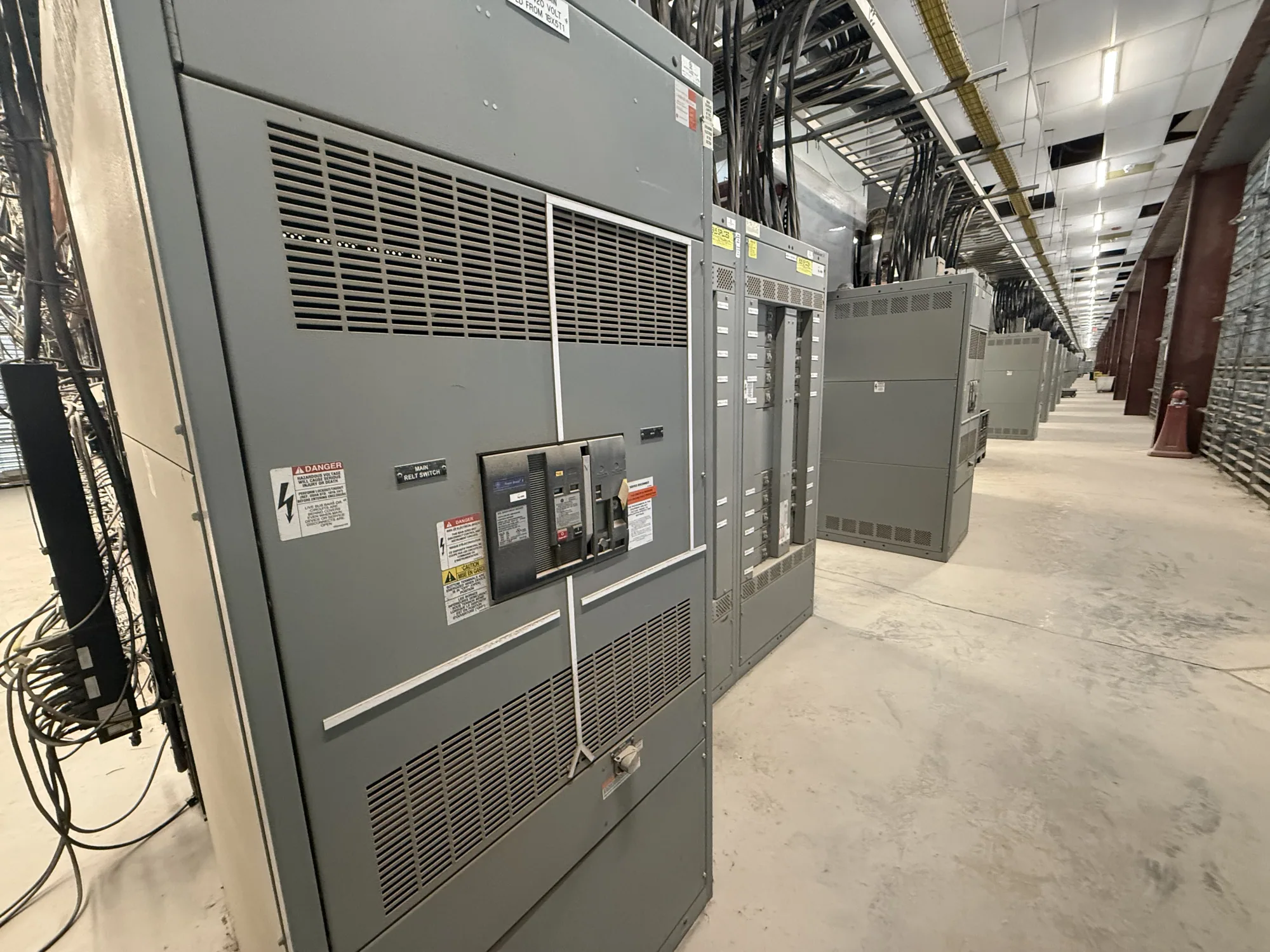
Neutral bus definition and scope
A neutral bus is a conductive bar or assembly that connects neutral conductors within electrical distribution equipment when the system design calls for one. It provides a common termination point for those conductors. The bus is part of a larger electrical arrangement, not a standalone method of grounding or a substitute for the system neutral conductor.
Neutral conductors are associated with the grounded circuit conductor in applicable system configurations. Their role depends on the source, connected loads, and design. A neutral bus may appear in a switchboard or other equipment when required by the specified arrangement. Its presence, construction, and connections should be established from the project documents and equipment drawings rather than assumed from the equipment name.
How it differs from a ground bus
A neutral bus and a ground bus are not interchangeable terms. A neutral bus serves neutral conductors; a ground bus provides termination for equipment grounding conductors and other grounding connections as specified. The functions are related through the overall grounding and bonding design, but that does not mean the two buses should be connected together at every distribution point.
Where neutral-to-ground bonding belongs depends on the system configuration and applicable requirements. For example, source arrangements and separately derived systems can affect where the project engineer specifies a bond. Treating every neutral bus as bonded to the enclosure, or assuming the buses must always remain isolated, can both lead to incorrect conclusions. The responsible engineer should define the intended relationship for the actual installation.
Why the distinction matters in switchboards
For a new electrical switchboard, the neutral bus can affect conductor landing arrangements, compartment layout, and coordination between the equipment design and the installation drawings. A buyer should identify whether neutral conductors are present in the circuits served, what conductors must terminate in the assembly, and how the specified system treats neutral and grounding connections. These details support a configuration matched to the project.
Switchboard designs are project-specific. The equipment specification should make clear which incoming and outgoing circuits require neutral connections, how those connections are arranged, and what grounding and bonding provisions are needed. If the scope, source configuration, or load information is incomplete, ask the project engineer to resolve it before finalizing the equipment design. Do not infer bus arrangement or rating from a general product description.
Conceptual example and common misunderstandings
Consider a conceptual switchboard serving several loads, with the assumption that the project design requires neutral conductors for some outgoing circuits. The neutral bus would provide the specified termination point for those conductors. The equipment grounding conductors would follow the grounding arrangement shown in the project documents, using the grounding provisions specified for the assembly. This example illustrates terminology only; it does not establish a bond location or equipment configuration.
A common misunderstanding is that “neutral” and “ground” describe two names for the same conductor or bus. Another is that a neutral bus always carries a particular current under every operating condition. Actual conductor use depends on the circuit and system design. A further mistake is to treat a ground bus as a neutral bus simply because both are conductive bars mounted inside distribution equipment.
What to confirm before specifying equipment
Before requesting a new switchboard, provide the project’s one-line diagram and identify the source arrangement, system voltage information, incoming and outgoing circuits, and which circuits require neutral conductors. Clarify the intended neutral-to-ground bonding location and the required grounding connections with the responsible electrical engineer. Include applicable drawings and specifications, and identify unresolved design questions instead of leaving the supplier to infer them.
Ask the equipment supplier to confirm how the requested neutral and ground bus provisions will be represented in the proposed assembly drawings. Review termination locations and the relationship to the enclosure and other components against the project documents. Any bus sizing, ampacity, fault-duty requirements, listing applicability, and construction details must be confirmed for the specific design; a glossary definition does not establish those values or claims.
Coordination from design through installation
Use consistent terminology across the one-line diagram, equipment specification, and installation documents. If the project changes its source arrangement or adds circuits needing neutral conductors, revisit the bus provisions and bonding instructions before approving the equipment drawings. A coordinated review helps reveal mismatches between the intended electrical system and the requested distribution assembly while changes are still being evaluated.
For a focused review, share the design documents and ask the project engineer to confirm neutral treatment, bonding points, and conductor termination needs. The supplier can then evaluate the requested new equipment configuration against the approved specification. Installation, testing, and maintenance should be performed by qualified personnel following applicable safety procedures. Related concepts include grounding and bonding, ground buses, and switchboard specifications; each addresses a different part of the complete system design.