Protective relay: a precise definition
A protective relay is a device that monitors specified electrical conditions and initiates a protective action when those conditions meet defined criteria. Depending on the design, it may receive measurements from current or voltage sensing devices, evaluate them against configured functions and settings, and issue an output to a circuit breaker or another control device. The relay detects and signals; it does not, by itself, interrupt fault current.
In electrical distribution, “protective relay” describes a role rather than one universal device or setting. Relays can support different protective functions, and the appropriate functions depend on the system, equipment, and responsible engineer’s protection design. A relay’s presence does not establish that a particular protection scheme is adequate, coordinated, or suitable for every operating condition.
How sensing and trip interfaces fit together
The relay must receive inputs that correspond to the quantities its functions are intended to evaluate. A current transformer, or CT, can provide a current signal for designated protection or measurement functions. Voltage sensing may also be part of a scheme where the selected functions require it. The engineer needs to identify the sensing devices, signal connections, ratios or other applicable data, and intended use; compatibility should be confirmed for the actual equipment design.
When configured conditions are met, the relay may operate an output connected to a breaker trip circuit or another specified control interface. The breaker performs the switching action, while the relay provides the decision and command. Control power, output contact arrangements, wiring, breaker interfaces, indication, and any communications needs therefore matter during specification. These details are design-dependent and must be verified rather than assumed from the word “relay.”
What it means in low-voltage switchgear
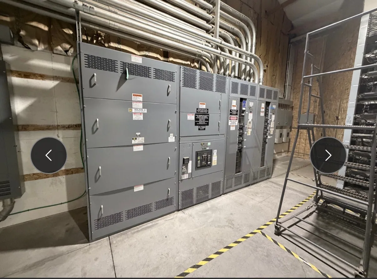
For a new low-voltage switchgear project, relay selection belongs within the complete protective scheme, not as an isolated component choice. A project team may need to establish which feeder or source is protected, what conditions the relay should detect, how it interfaces with the associated breaker, and how its settings relate to upstream and downstream devices. The responsible engineer determines the applicable functions and coordination approach for the installation.
Switchgear configuration and relay requirements should be reviewed together. Space, mounting, wiring access, sensing connections, control power, breaker trip interfaces, and desired operator indications can affect the equipment design. Available functions and options depend on the specified relay and assembly. If a low-voltage switchboard is being considered instead, distinguish that product from switchgear and confirm the intended equipment type, ratings, and applicable assembly requirements against the project specification.
Conceptual example and common misunderstandings
Assume a project engineer is defining protection for a low-voltage feeder in new switchgear. The engineer identifies the conditions to monitor, selects compatible sensing inputs, defines the protective functions and settings, and specifies how the relay output should interact with the feeder breaker. This is a conceptual sequence, not a recommended setting or a claim about any particular system. Actual design depends on documented system information and engineering review.
A common misunderstanding is to treat a relay as interchangeable with a breaker. They have related but distinct roles: the relay detects and commands, while the breaker makes or interrupts the circuit as designed. Another is to assume that the same relay settings work across installations. Settings and coordination are system-specific. A relay’s display, alarms, or communications features also do not substitute for the required protective functions or prove that a protection scheme has been validated.
Questions to resolve before specifying a relay
- Which equipment section, source, or feeder is the relay intended to protect, and what protective functions are required by the project design?
- What current or voltage sensing inputs are needed, and what CT or other sensing-device information must match the relay?
- How will the relay be powered, wired, and connected to the breaker trip circuit or other control interface?
- Who will establish settings and verify coordination with the rest of the distribution system?
- Are operator indication, alarms, communications, or event information required, and which features are actually specified?
Providing the one-line diagram, equipment schedule, available sensing-device information, breaker details, control requirements, and project specifications helps the manufacturer assess the requested configuration. The project engineer should identify any unresolved protection decisions; a supplier should not infer settings or coordination requirements from an incomplete equipment description.
From definition to a project specification
This glossary definition explains what a protective relay does. A specification guide addresses the separate process of selecting and documenting one for a project, including the information needed to evaluate functions, inputs, interfaces, and equipment integration. South Carolina Switchgear Builders manufactures new equipment to specification, with US-built equipment, all-American components, and nationwide shipping. Configuration, availability, and actual lead times depend on the order and must be confirmed.
For a project discussion, submit the equipment type, voltage class, intended application, design documents, and known relay and breaker requirements. Confirm ratings, listing applicability, testing, and delivery details for the proposed assembly and specification. Installation, testing, and maintenance should be performed by qualified personnel following applicable safety procedures. Clear division of responsibility among the engineer, equipment manufacturer, and installation team helps carry the relay’s protective role into a coherent equipment design.