What electrical shop drawings mean
Electrical shop drawings are project-specific drawings prepared to show how proposed equipment is configured for a particular project. For switchgear and switchboards, they may communicate the assembly arrangement, major components, electrical connections, dimensions, interfaces, and other details needed for review and coordination. The required content depends on the purchase documents, project specifications, and the equipment being supplied.
These drawings are submitted for review under the agreed project process; they are not automatically the original design documents, a substitute for the project engineer’s decisions, or proof that an assembly meets every code or specification. Their purpose is to make the proposed equipment design visible enough for the responsible parties to identify discrepancies, resolve interfaces, and confirm requirements before the applicable production or project milestones.
How they relate to design documents and standards
Contract drawings and specifications generally establish the project’s design intent and requirements. Shop drawings show how a supplier proposes to configure equipment to meet those requirements. The two document sets serve different roles: a supplier’s drawing should not silently revise the engineer’s design, and a review stamp should not be treated as a blanket transfer of design responsibility. The project documents define the actual review and approval process.
Applicable codes, product standards, utility requirements, and authority having jurisdiction expectations must be assessed for the specific project and assembly. For example, UL 891 concerns eligible low-voltage switchboards, but its applicability and any assembly listing must be verified for the particular design. It is not a general designation for all switchgear, and it does not apply to medium-voltage switchgear. Drawings can help document intended construction; they do not by themselves establish compliance or listing.
What low-voltage equipment drawings may clarify
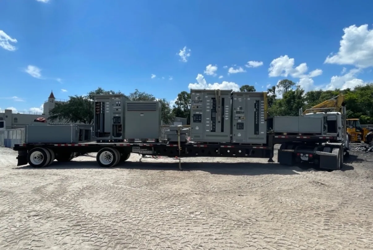
For a new low-voltage switchgear project, a drawing package may show the lineup layout, section arrangement, incoming and outgoing connections, equipment interfaces, and physical dimensions. Depending on the contract, it may also include one-line or elementary diagrams, schedules, terminal information, or other coordination details. The buyer should confirm the required submittal list rather than assume every supplier’s package uses the same content or naming conventions.
Physical coordination can be just as important as circuit information. The project team may need to compare the proposed footprint and access clearances with the electrical room, confirm conduit or cable entry assumptions, and coordinate connections to other equipment. These details depend on the installation and the approved design. A drawing should identify unresolved assumptions clearly enough that the engineer, contractor, and supplier can address them before they become field conflicts.
Conceptual example: review the interface, not just the layout
Assume a project specifies a new low-voltage switchgear lineup and the equipment supplier submits a proposed arrangement for review. The reviewer compares the drawing with the project one-line diagram, equipment schedule, room plan, and written requirements. If the drawings depict a different connection arrangement or an entry location that conflicts with the room plan, the team records the discrepancy and asks the responsible designer and supplier to resolve it. No ratings or dimensions should be inferred when they are not stated.
This example illustrates why “reviewed” does not necessarily mean “approved for every purpose.” The reviewer should distinguish a confirmed requirement from an open question, and the supplier should identify design-dependent details that need direction. A drawing review is also not an instruction to perform electrical work while equipment is energized; installation, testing, and maintenance are for qualified personnel following applicable safety procedures.
Common misunderstandings and related terms
Shop drawings are not the same as a generic product brochure, a preliminary quotation, or an as-built record. A brochure describes product capabilities broadly; a project submittal addresses a particular proposed configuration. As-built documents record the installed condition when required and prepared through the project’s closeout process. A shop drawing may change during review, so the team should track revisions and identify which version is current.
“Submittal” often refers to the broader package and review process, while shop drawings are one possible component. Specifications and codes establish requirements or design criteria, but the exact relationship depends on the contract and applicable rules. The project engineer, supplier, contractor, and authority having jurisdiction each have distinct responsibilities; no single drawing or review notation should be assumed to satisfy every party’s obligations.
Questions to settle before review and release
- Which drawings and supporting documents does the purchase specification require, and who reviews each item?
- Do the proposed diagrams and equipment arrangement correspond to the approved project documents, including stated interfaces and connection assumptions?
- Which dimensions, clearances, cable or conduit entry points, and room conditions must the contractor or engineer verify?
- Are applicable standards, listing expectations, utility requirements, and authority having jurisdiction questions identified for confirmation by the responsible parties?
- How will comments, revisions, approval status, and any unresolved exceptions be recorded before the next project milestone?
Provide the supplier with the current project specifications, relevant drawings, equipment schedule, installation constraints, and a clear list of required submittals. Confirm the review sequence, revision method, and any information that remains subject to engineering direction. For new equipment built to specification, careful coordination between the buyer, project engineer, contractor, and manufacturer helps make the proposed configuration understandable and reduces avoidable ambiguity before the project proceeds.