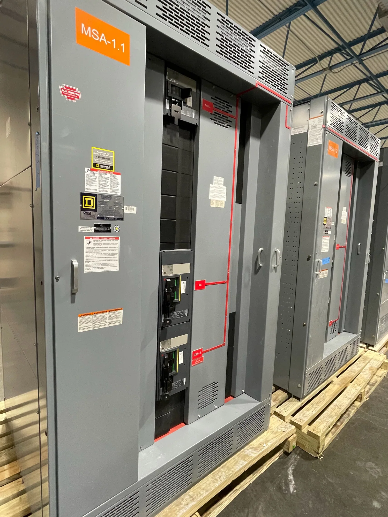
What a transfer switch does
A transfer switch is a device designed to transfer an electrical load from one source of power to another. Depending on the system, the sources might include normal utility service and an alternate source such as a generator. The switch establishes which source supplies the designated load, following the equipment’s operating design and control scheme.
The term describes equipment, not a complete backup-power system or a guarantee that loads will remain energized. Source availability, transfer timing, transition method, protection, and the loads selected for transfer are project-specific. The responsible engineer defines how the arrangement should operate and confirms that the equipment and controls match that intent.
Transfer switch, transfer action, and related equipment
A transfer switch is the device; transfer is the action of moving a load between sources. A specification guide, by contrast, explains how to communicate requirements for equipment and interfaces. Keeping those meanings separate helps a project team distinguish a glossary definition from the detailed decisions needed to procure new distribution equipment.
A transfer switch should also not be confused with generator-paralleling equipment. A transfer arrangement selects between sources according to its design, while paralleling involves operating sources together under a coordinated scheme. Whether sources can operate simultaneously, whether an interruption is acceptable, and how interlocking prevents unintended connections must be established for the particular system.
Design considerations for distribution projects
Selection begins with the electrical one-line diagram and the intended load-transfer sequence. The engineer should identify each source, the loads served, operating modes, and the conditions that initiate or inhibit transfer. The equipment design must also account for the applicable voltage class, current and fault-duty requirements, enclosure and installation conditions, and protection coordination, as verified for the actual project.
Control and instrumentation requirements deserve equal attention. Identify required status indications, alarms, metering values, remote commands, and monitoring points, then define where each signal originates and where it must be delivered. If communications are required, specify the needed protocol and network interface rather than assuming that a particular device or connection is included in the switchgear assembly.
Define the cybersecurity boundary with the project’s controls and information-technology teams. Clarify whether monitoring is read-only, what remote control is permitted, how access is managed, and which party supplies or configures network equipment. These decisions help prevent a gap between the switchgear control design and the facility’s operating policies. Instrumentation and communications requirements should be documented alongside the electrical sequence.
Illustrative service-entrance context
Consider a conceptual facility project with utility service, a generator, and selected loads intended for alternate-source operation. Assume only that the engineer has identified a need to transfer those loads; no specific voltage, capacity, transfer timing, or equipment rating is implied. The engineer would determine the service arrangement, the point of transfer, protection and isolation needs, and whether service-entrance switchgear is part of the same coordinated design.
In that example, the transfer function and service-entrance equipment are related but not interchangeable terms. The project team should confirm how the transfer device integrates with the distribution lineup, which loads remain outside the alternate-source scheme, and what status or metering information operators need. Any service-entrance designation, listing, ratings, and assembly configuration must be confirmed for the actual equipment specification.
Operating choices and common misunderstandings
Transfer designs can involve different transition approaches, control logic, and operating sequences. The project engineer should determine whether the load may experience an interruption, what conditions permit a transfer, and whether return to the preferred source is automatic or requires an operator action. Do not infer these capabilities from the phrase “transfer switch”; they depend on the specified equipment and control scheme.
Another common misunderstanding is treating a transfer device as a generator controller, protective relay, or complete emergency-power system. Those functions may be coordinated with transfer equipment but are distinct design responsibilities. The one-line diagram, sequence of operation, and equipment documents should show how sensing, protection, source control, and load selection work together. Qualified personnel must handle installation, testing, and maintenance under applicable safety procedures.
Information to clarify before specifying equipment
- Which sources are involved, and which loads must each source serve?
- What sequence, transfer conditions, and return-to-normal behavior are required?
- What electrical, environmental, and installation requirements apply?
- Which metering, alarms, status points, remote commands, and communications interfaces are needed?
- How must the transfer function coordinate with service-entrance equipment, protection, and other source controls?
- Which party provides control devices, network connections, configuration, and project approvals?
Provide the supplier with the current one-line diagram, load and source information, operating sequence, interface requirements, and any project specifications. Ask the responsible engineer to resolve open questions before equipment is finalized. A manufacturer can then review the requested configuration against the supplied requirements; availability, lead time, ratings, listing, and delivery details require confirmation for the specific order.
From definition to project specification
Use “transfer switch” precisely when identifying the device that transfers designated loads between sources, and use the project documents to define how it must perform. That distinction supports clearer coordination among electrical design, controls, operations, and equipment procurement without assuming functions that have not been specified.
For new distribution equipment, the next step is to document the source arrangement, load priorities, transfer sequence, and instrumentation or communications needs, then review them with the project engineer and equipment supplier. Clear requirements make it easier to evaluate how the transfer function fits the broader distribution system and what must be confirmed before an order is placed.