Define the plant electrical scope
Power-plant switchgear is not a single, interchangeable package. A project may involve generator connections, auxiliary distribution, station service, and ties to an external source or export system. Begin by identifying which portions of the electrical system the new equipment must serve, what lies outside the package, and where responsibility passes to other equipment or project teams.
For example, a hypothetical generating facility might need a switchboard for low-voltage auxiliary loads and separate medium-voltage gear for a source or distribution interface. That is only a planning scenario, not a prescribed design. The plant one-line diagram, voltage classes, operating modes, and engineering studies determine whether those functions belong in one or multiple assemblies.
Separate generation, auxiliary and export interfaces
Generator-side equipment, auxiliary distribution, and an export connection have different purposes and should be described separately in the scope. Identify each source and bus, the normal and alternate feeds, and any connection points to transformers or downstream distribution. Clarify whether the requested package includes switching and protection functions at each boundary or only equipment within a defined lineup.
Station-service loads can include systems needed to operate the facility, but the actual load list varies by plant. Provide load names, operating and starting characteristics where available, and which loads must remain supplied in each operating state. The responsible engineer should confirm how source transfers, generator startup, shutdown, and loss-of-source conditions affect the required equipment and control logic.
Coordinate source behavior and protection
Protection depends on more than the nominal voltage. Provide available fault-current information at the proposed connection points, source and transformer data, grounding approach, and the results or assumptions of applicable coordination studies. The project engineer must establish required interrupting and withstand duties and verify that the proposed assembly and components suit the specific system conditions.
For generation projects, relay functions and settings may depend on generator characteristics, operating modes, utility or grid interfaces, and the protection philosophy. Share the intended trip logic, monitored quantities, interlocks, and required signals, while leaving settings and application decisions to the responsible protection engineer. Equipment configuration and relay selection should be reviewed against the project study rather than inferred from a generic plant description.
Choose maintainability and operating arrangements
Plan how operators are expected to isolate equipment and maintain continuity to critical auxiliaries. The required arrangement depends on the plant’s operating priorities, redundancy strategy, space, and procedures. Discuss bus segmentation, source separation, spare provisions, and any desired transfer capability with the project team; these choices can change lineup arrangement, controls, and the interfaces that must be documented.
Room dimensions, access routes, cable entry, conduit locations, environmental conditions, and working clearances can constrain equipment selection. Provide available drawings and identify installation access limits early. Qualified personnel must perform installation, commissioning, testing, and maintenance under applicable safety procedures. The equipment supplier can coordinate dimensions and connection details, but should not substitute for the project’s installation design or safety planning.
Resolve trade-offs and design assumptions
A compact lineup may reduce room or routing demands, while greater separation or additional sections may support a project’s preferred operating and maintenance approach. Neither arrangement is universally better. Compare the actual footprint, connection scheme, access, fault-duty requirements, control boundaries, and expansion needs before fixing the specification. Confirm that assumptions about future units or spare capacity are explicit rather than left to interpretation.
Also distinguish the equipment’s voltage class and function. A 480 V class assembly is low voltage; 5 kV and 15 kV class equipment are medium voltage. A low-voltage switchboard specification should not be applied to medium-voltage switchgear. For eligible low-voltage switchboards, any UL 891 applicability and assembly listing must be verified for the specific design; do not assume it applies to every configuration or to medium-voltage equipment.
Prepare a useful equipment request
A clear request for quotation should include the latest one-line diagram, system voltage, source and transformer information, fault-duty requirements, auxiliary load schedule, and the intended operating sequence. Add protection and control requirements, interface points, cable and bus connection details, drawings, environmental conditions, and any project-specific listing or documentation requirements for review.
- Identify generating sources, normal and alternate feeds, and export or utility boundaries.
- Describe auxiliary loads, priority loads, starting needs, and required operating states.
- Provide available fault-current data, grounding details, and relevant study assumptions.
- State relay, control, interlock, communication, and alarm requirements.
- Include room layout, access constraints, installation schedule, and responsible project contacts.
Coordinate the new equipment package
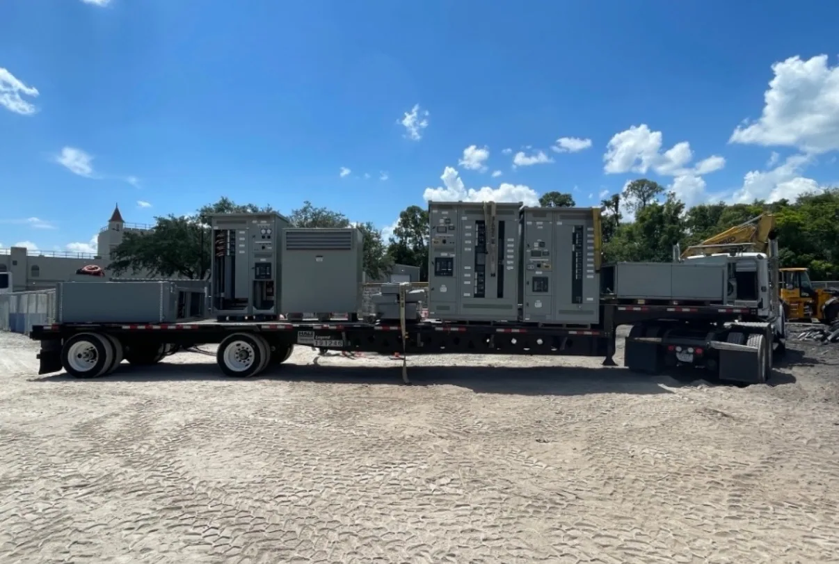
South Carolina Switchgear Builders manufactures new switchgear and switchboards in the United States using all-American components, with custom configurations built to specification and nationwide shipping. Availability and lead times depend on the order and must be confirmed. Share the project scope early so equipment boundaries, technical assumptions, drawings, and delivery coordination can be reviewed before they become schedule constraints.
During procurement, keep the one-line diagram, load schedule, protection basis, and equipment drawings aligned as the design develops. Confirm revisions, approval responsibilities, shipping destination, site access, and the required delivery window with the project team. Final ratings, availability, dates, testing, and any listing or standards applicability require confirmation against the actual specification and supplied equipment. This discipline gives the plant team a defined basis for evaluating new switchgear against its generation and station-service needs.