Scope for aerospace manufacturing projects
Aerospace manufacturing facilities can bring precision production, inspection, test equipment, environmental controls, and process-support loads together across a changing electrical system. Arc-flash planning should account for the actual equipment and operating conditions involved, not assume that one switchgear design or protective device resolves risk throughout a facility. The right starting point is a qualified engineering review tied to the project boundary.
Owners, facility engineers, electrical engineers, safety leaders, production teams, and equipment suppliers may each hold information that affects the design. A new equipment project can touch an existing distribution system, a new production area, or a phased capacity change. Clarify which portions are being evaluated, what will remain in service, and who is responsible for study assumptions, field verification, equipment selection, and work-practice decisions.
Study inputs and operating scenarios
An arc-flash assessment depends on a documented electrical model and verified inputs. The responsible engineer may need utility or source data, transformer information, conductor lengths and sizes, protective-device types and settings, equipment configuration, and available operating modes. Where details are unknown, record the uncertainty for resolution; do not treat an assumed value as a verified site condition. The study boundary and intended use should also be clear.
Production facilities may operate with alternate sources, tie breakers, temporary configurations, or staged additions. These arrangements can change available fault current and protection behavior, so the engineer should identify which normal and credible alternate configurations merit evaluation. A future expansion or planned maintenance state may also affect the study. Determine how configuration changes will be documented and whether a revised analysis is needed before equipment is operated in a changed arrangement.
Protection coordination and quality-sensitive loads
Protection coordination balances fault clearing, equipment protection, and continuity of service. A setting that reduces exposure under one condition may affect selectivity or cause a broader outage under another. The project engineer should evaluate device characteristics, upstream and downstream relationships, and applicable operating cases rather than select settings from an isolated equipment label. Any proposed adjustment should be reviewed for its system-wide consequences.
In aerospace manufacturing, an interruption can affect controlled processes, test sequences, environmental conditions, or production scheduling. That concern does not justify compromising protective functions. Instead, identify loads that require orderly shutdown, continuity, or restart review, and coordinate those needs with the electrical design and operations team. Capture acceptable interruption assumptions and restart constraints early so they inform distribution choices without being mistaken for an arc-flash control by themselves.
Equipment choices and work practices
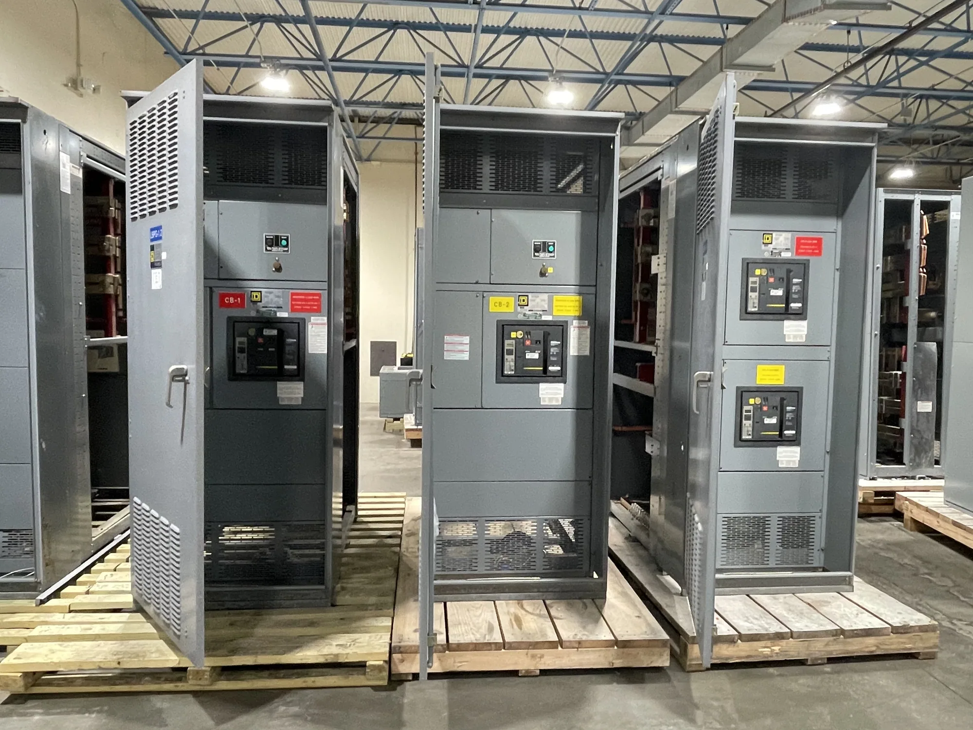
Low-voltage switchgear may be one interface in a facility distribution project, but it is not automatically required for every aerospace application. The responsible engineer should determine voltage class, system arrangement, ratings, protective devices, metering, enclosure, access, and connection requirements from the project specification. For new custom equipment, provide the one-line diagram, available system data, operating configurations, and interface requirements to the manufacturer for review.
Equipment design features and protective-device options may influence how a system is operated or maintained, but no selection alone eliminates arc-flash risk across a facility. Incident energy and boundaries must be based on the applicable study and its assumptions. Qualified personnel must follow the employer’s electrical safety program, equipment instructions, and applicable procedures for task planning, protective measures, and access. Installation, testing, and maintenance belong to qualified personnel; energized work should never be treated as the default project approach.
Phased changes and project coordination
When construction or production upgrades proceed in phases, define the limits of each phase and the electrical configuration expected at each handoff. Coordinate outages, temporary connections, commissioning responsibilities, and protection-setting control with the owner and qualified project team. Confirm whether study documents and equipment labels must reflect interim states, the final configuration, or both. Maintain clear revision control so field teams are not relying on superseded drawings or settings.
For a new equipment order, agree on drawing review milestones, required submittals, connection details, and the information needed before manufacturing. Confirm project-specific ratings, listing applicability, testing scope, delivery dates, and availability against the actual specification; these are not universal assumptions. US-built equipment with all-American components and short lead times may be available, but configuration and timing depend on the order and must be confirmed. Nationwide shipping is available.
Buyer and engineering checklist
Before requesting a proposal, assemble the current one-line diagram, source and transformer data, protective-device schedules, known settings, load and operating-mode descriptions, and any study requirements. Identify new loads, planned phases, physical constraints, preferred interfaces, and the parties authorized to approve technical changes. If information is incomplete, list open items and assign responsibility for verification rather than silently filling gaps.
Ask the responsible engineer to state study assumptions, system cases, deliverables, and review responsibilities. Ask the equipment supplier how the proposed assembly addresses the documented specification and what drawings or decisions are needed to proceed. Review the design with facilities, production, safety, and maintenance stakeholders before release. A coordinated specification, qualified study, and maintained work-practice program give the project a sound basis for safer decisions as aerospace operations and electrical configurations evolve.