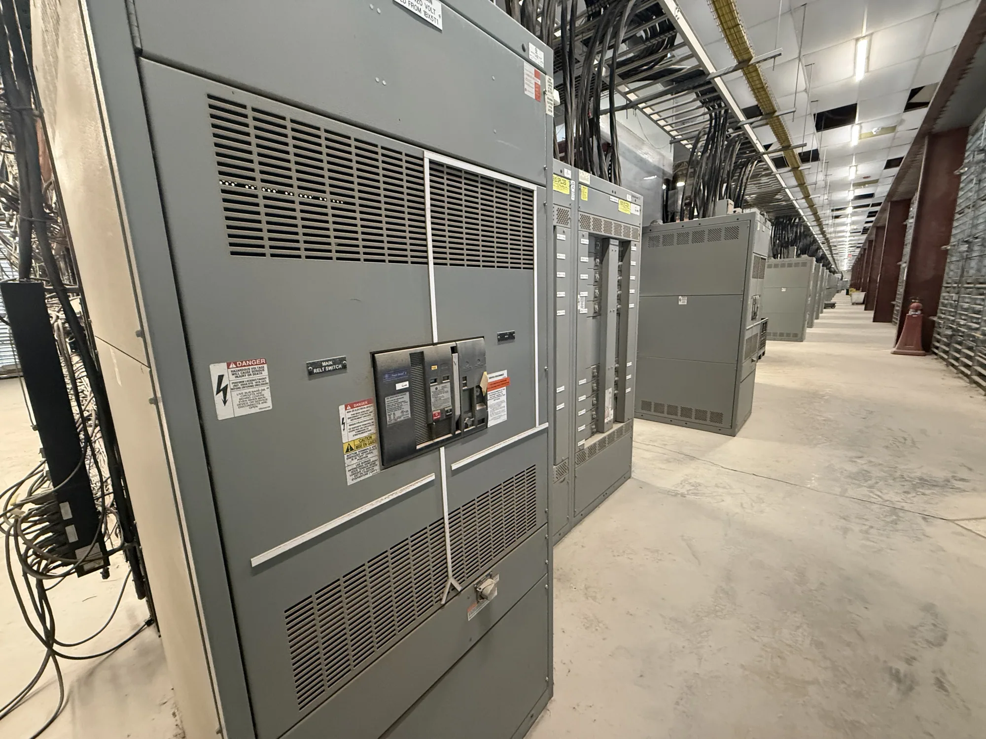
Start with the facility system, not a single rating
In an aerospace manufacturing facility, electrical distribution may support precision production equipment, test areas, environmental systems, utilities, and building loads. Each part of the system can have different operating needs and different fault-current conditions. Short-circuit planning is therefore a facility-wide engineering task, not simply a matter of choosing the largest rating printed on one switchgear lineup.
The responsible electrical engineer should establish the system boundaries and identify the equipment under consideration. A project may involve a new service, a replacement section, an added production area, or a phased expansion. Those situations affect what information is available and which upstream and downstream equipment must be reviewed. Manufacturer selection follows the project design; it does not replace system analysis.
Determine available fault current at each connection
Available fault current is the prospective current at a specific point in the electrical system under defined conditions. It depends on the source and the intervening system, so it may differ from one bus or piece of equipment to another. The engineer should use project-specific source data and system assumptions, including any relevant transformer and conductor information, rather than carry one facility value across every distribution point.
Compare the calculated available fault current with the applicable ratings of each proposed assembly and its protective devices. Interrupting capacity describes a protective device’s ability to interrupt fault current under its specified conditions. Assembly withstand or short-circuit current ratings address the assembly’s ability to withstand fault effects, as defined for the particular design. These are related but distinct checks; a favorable value for one component does not establish that the complete equipment arrangement is suitable.
Coordinate protection with production priorities
Protection coordination evaluates how protective devices respond to faults across a system. For quality-sensitive operations, the engineer may need to consider which equipment should disconnect for a fault and what other loads could be affected. The goal is not simply to maximize continuity at any cost: safety, equipment limits, system design, and the applicable engineering criteria remain central. The coordination study and project requirements should guide device selection and settings.
Fault-current ratings and coordination are connected, but they answer different questions. A rating comparison addresses equipment capability under specified conditions; coordination concerns the behavior of protective devices in relation to one another. Ask the engineer to identify the assumptions behind both reviews and whether proposed changes alter the study. Adding a transformer, changing a source, or extending a feeder can affect the available fault current or the way protection operates.
Assess phased changes and future interfaces
Phased aerospace projects can make system boundaries especially important. A new production line may connect to an existing distribution system while later phases remain conceptual. The project team should distinguish verified existing conditions from design assumptions and identify which future connections have been included in the analysis. Do not treat an anticipated expansion as harmless or assume that equipment selected for an earlier phase will suit every later configuration.
When considering low-voltage switchgear, treat it as one possible interface within the engineered system, not an automatic requirement for every aerospace facility. The project documents should establish the voltage class, arrangement, protective devices, connection points, and ratings needed for the actual application. Confirm whether the proposed equipment is a switchboard or switchgear and which standards and listing requirements apply to that specific design; UL 891 applies to eligible low-voltage switchboards, subject to assembly-specific verification.
Bring the right project information to the supplier
A useful equipment inquiry gives the manufacturer the design basis rather than only an industry label. Provide the one-line diagram or relevant system drawing, nominal voltage, available fault current at the connection, and the engineer’s required device and assembly ratings. Include source and transformer data where available, protective-device preferences or constraints, physical arrangement, environmental conditions, and any requirements for future sections or connections.
Also identify what is confirmed and what remains subject to engineering review. State the applicable project standards, required documentation, testing expectations, listing needs, and any procurement or delivery constraints for the specific order. If the analysis or ratings are still being developed, say so; the manufacturer can review the information supplied and identify questions, but the responsible engineer must establish the system requirements. Availability and lead time depend on the order and require confirmation.
Use a review checklist before releasing the design
Before approving new equipment, have the owner, electrical engineer, protection or controls stakeholders, and supplier review a consistent set of project inputs. Confirm the connection point, system voltage, available fault current, interrupting and assembly ratings, protective-device coordination, and the assumptions for each project phase. Resolve discrepancies between drawings, studies, and procurement documents before equipment configuration is finalized.
- Identify the loads and production areas served, including planned phase boundaries.
- Confirm source data, fault-current calculations, and ratings at each relevant point.
- Document protection coordination criteria and review any proposed system changes.
- Specify equipment type, configuration, applicable standards, and assembly-specific listing or testing requirements.
- Assign responsibility for engineering approval, supplier submittal review, and schedule confirmation.
South Carolina Switchgear Builders manufactures new equipment to specification, with US-built equipment and all-American components, and ships nationwide. The project team should confirm the actual configuration, applicable ratings, documentation, availability, and delivery timing against the approved design and order. Qualified personnel must handle installation, testing, and maintenance under applicable safety procedures. A clearly reviewed design basis gives the manufacturer and project stakeholders a sound starting point for supplying equipment that fits the facility’s engineered distribution plan.