Start with the production system
Protective relay selection for automotive manufacturing begins with the electrical system the relays must protect, not a preferred device model. A hypothetical facility may include production lines, large motor loads, process utilities, material handling, and planned expansion. Map how these loads connect to sources, transformers, buses, and feeders, then identify which portions of production depend on each electrical path.
This facility-wide view helps owners and engineers consider how a fault, planned outage, or equipment change could affect operations. Separate essential process loads from loads that can be interrupted where the operating plan supports that distinction. Record existing equipment interfaces and anticipated additions, but treat future loads as design assumptions until their electrical characteristics and timing are confirmed.
Define protection objectives and boundaries
For each protected zone, the responsible engineer should define the conditions the scheme is intended to detect and the equipment it is intended to isolate. Depending on the system design, functions may address overcurrent, ground-fault conditions, or other specified electrical hazards. The appropriate functions depend on the system study, equipment, grounding arrangement, and operating requirements; a feature list alone does not establish a suitable scheme.
Feeder segregation can support clearer boundaries between production areas, but it must match the one-line diagram and the actual switching arrangement. Ask which breakers or other interrupting devices a relay can command, what backup protection is expected, and how loss of a control circuit affects the intended response. Confirm that each protective zone has a defined interface and that overlapping or unprotected portions are addressed by the engineering design.
Match sensing, control power, and devices
Relay inputs must be compatible with the specified current and voltage sensing equipment, wiring, and system configuration. The project team should provide the relevant instrument-transformer data, polarity and connection assumptions, input requirements, and any restrictions on shared or dedicated sensing. Confirm the device documentation for supported functions and input ranges rather than assuming that relays with similar names accept the same signals.
Control power deserves equal attention, particularly where production continuity and outage planning matter. Identify the control-power source, its nominal characteristics, backup expectations, and the behavior required during a source interruption. Coordinate relay outputs with breaker trip circuits, alarms, interlocks, and monitoring systems. The engineer should verify circuit details, failure indications, and test access against the complete control schematic and the selected devices.
Coordinate settings across production feeders
Relay settings are part of a protection study, not a supplier default. The engineer should assess available fault information, equipment limits, device characteristics, and the desired relationship among upstream and downstream protection. Selectivity and coordination goals must be evaluated for the actual system and operating modes; changes in sources, transformer configuration, or feeder loading may alter the study assumptions.
For staged outages, document which feeders may be isolated, what loads should remain supplied, and whether temporary operating configurations are anticipated. Provide the engineer with normal and alternate one-line diagrams, source and transformer data, load information, and known expansion plans. Have qualified personnel review and implement approved settings using the device manufacturer’s documentation and applicable safety procedures. Do not treat settings copied from a similar line as verified for this system.
Plan maintainability without losing production context
Maintainable distribution depends on more than relay access. Discuss how personnel will identify devices, retrieve settings, review event information, and conduct testing during planned work. Ask whether the specified communications and monitoring interfaces align with facility practices, and define who owns configuration records and revisions. Any testing or maintenance should be performed by qualified personnel following equipment instructions and the applicable safety procedures.
Outage planning should identify the affected production areas, required operating approvals, and dependencies on other systems. Consider whether feeder boundaries make isolation and restoration understandable to the people responsible for operations. These are design and operating questions for the owner and engineer; a relay or switchgear supplier can clarify equipment interfaces, but should not substitute for the facility’s protection study or operating procedure.
Give suppliers a coordinated specification
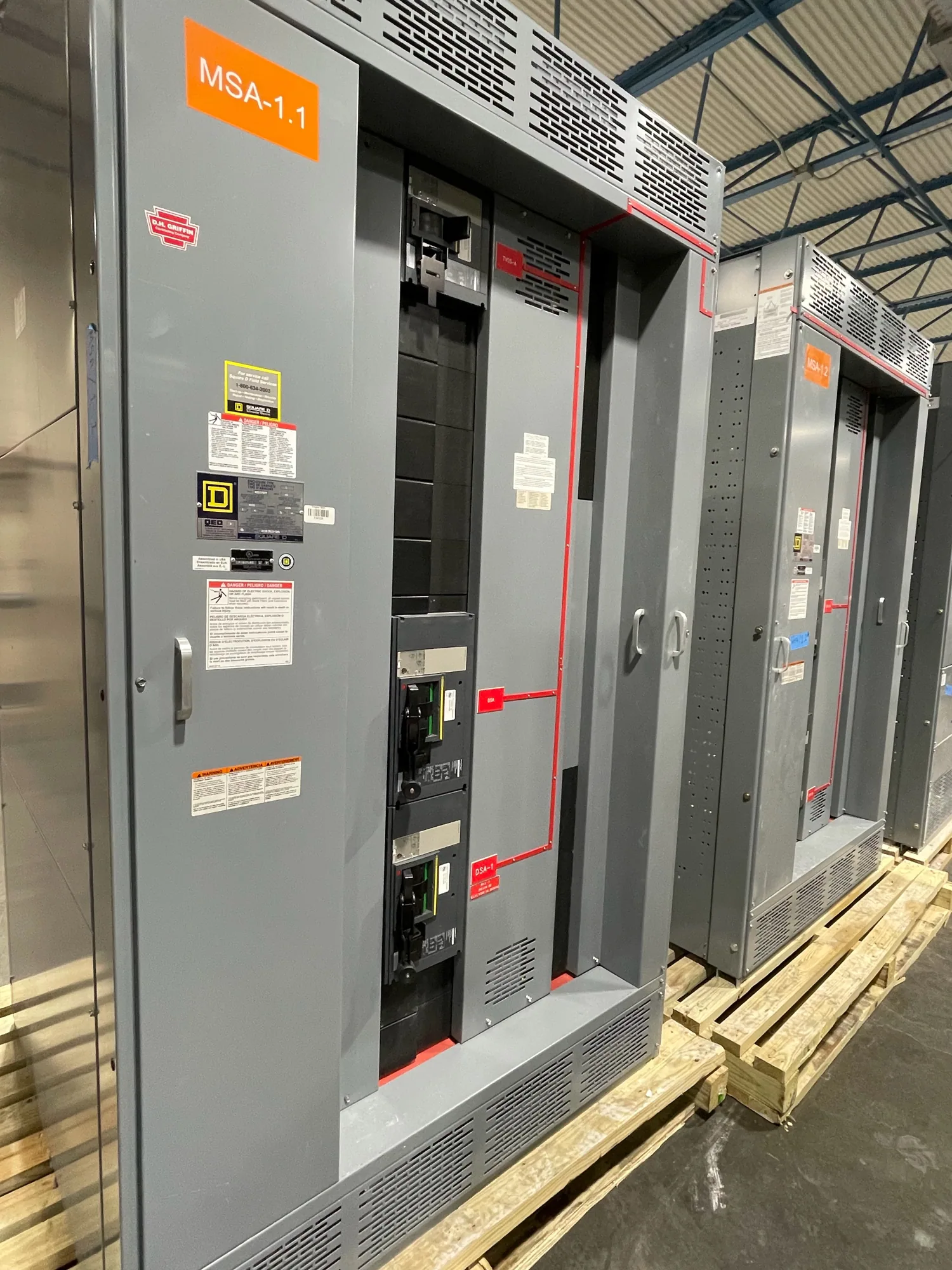
When requesting new switchgear or switchboards, provide the approved one-line diagram, system voltage class, source and transformer details, fault-study assumptions, protection functions, sensing requirements, control-power details, and interface expectations. Include enclosure and installation constraints, communication needs, project milestones, and planned expansion where known. Identify unresolved assumptions explicitly so reviewers can distinguish confirmed requirements from items needing engineering decisions.
Low-voltage switchgear may be one interface in a project, but it is not automatically required for every automotive manufacturing distribution design. Specify the equipment type and ratings only after the responsible engineer establishes them. South Carolina Switchgear Builders manufactures new equipment custom to specification, with US-built equipment and all-American components, and ships nationwide. Configuration, applicable listing, testing, availability, and delivery timing depend on the particular order and must be confirmed.
Use a project review checklist
Before release, bring the owner, electrical engineer, operations team, and equipment supplier together to confirm the one-line diagram, protection boundaries, relay functions, sensing and control-power interfaces, coordination-study responsibility, and outage assumptions. Review how production feeder segregation supports the operating plan and whether planned expansion is represented accurately. Confirm applicable standards and any listing requirements for the specific assembly; applicability depends on the equipment and design.
Close the review by documenting approved drawings, settings responsibility, device documentation, submittal decisions, and changes that require renewed engineering review. Verify the equipment specification, schedule, and delivery details against the actual project rather than relying on generalized expectations. This disciplined handoff gives the project team a shared basis for purchasing new distribution equipment and for maintaining protection decisions as the automotive facility evolves.