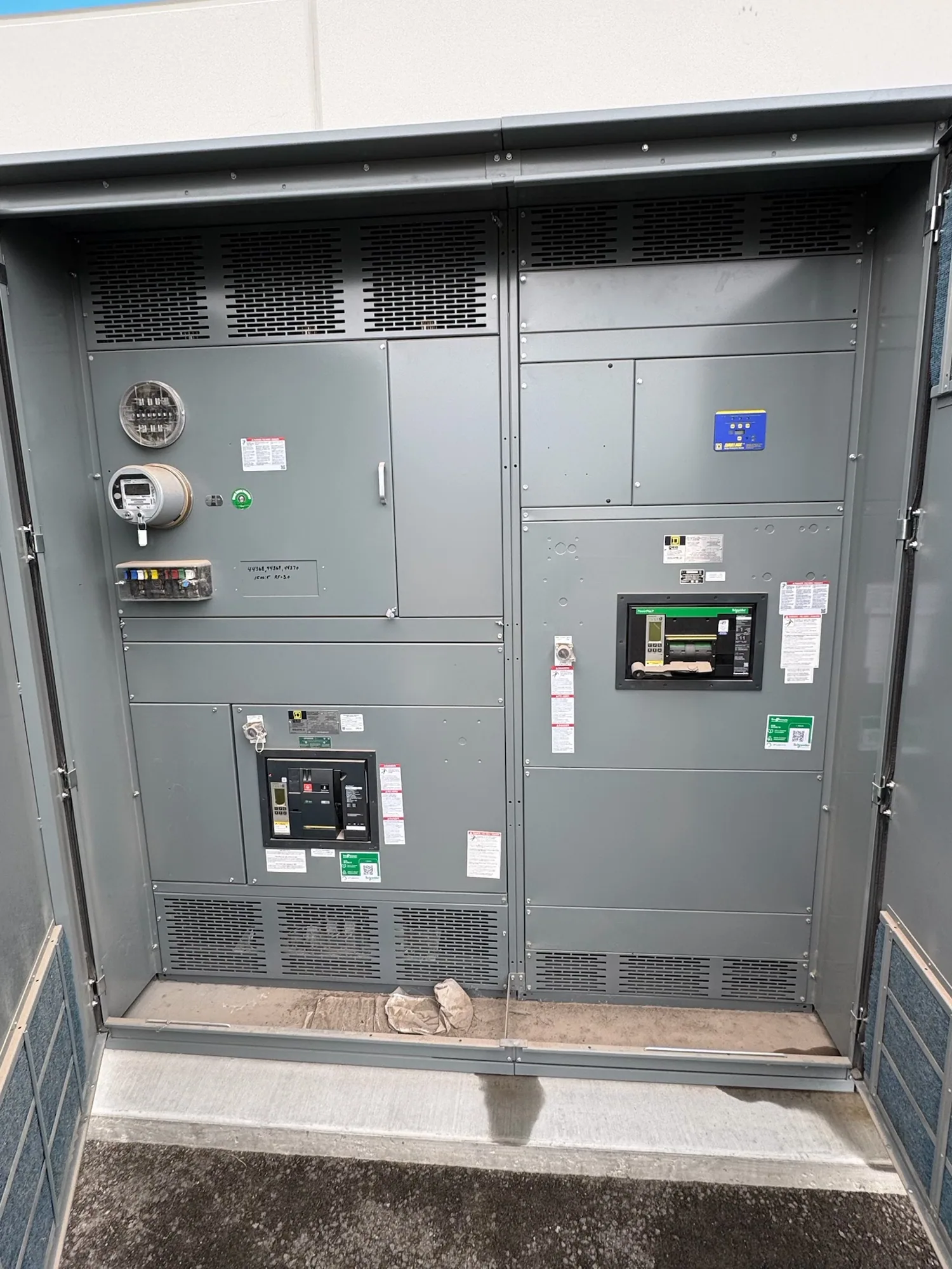
Scope: coordination across a production facility
Automotive manufacturing distribution can serve production lines, material handling, process equipment, utilities, and supporting spaces. A selective coordination plan considers how protective devices relate across the portions of the electrical system defined by the project. Its purpose is to limit an interruption to the affected portion when a fault occurs, while retaining the protective response required by the engineered design. The actual result depends on system conditions and device selections, not on a product label alone.
For a hypothetical facility with several production areas and planned expansion, the design team may need to consider which loads share feeders, which processes can tolerate an interruption, and how planned work can be isolated. Those questions connect coordination with feeder segregation and outage planning. They do not establish a particular arrangement as universally appropriate. The owner and responsible engineer must define operating priorities, system boundaries, and the applicable project requirements.
How protective-device coordination is evaluated
Selective coordination is assessed by comparing the time-current behavior of protective devices along relevant paths from a load toward its source. The engineer evaluates whether downstream devices can respond to specified fault conditions without unnecessarily operating upstream devices, within the limits and assumptions of the analysis. Device curves, available fault current, settings, tolerances, and the chosen coordination range all affect the conclusion. A review should make clear which devices and operating conditions were included.
Motor-driven production equipment adds practical questions. Starting and operating characteristics may influence protective-device selection, while short-circuit and ground-fault protection must remain consistent with the engineered system. The team should identify relevant motor loads and their protection requirements rather than assume that one setting approach works for every feeder. Where documentation shows an overlap or limitation in device behavior, the engineer can evaluate alternatives and explain the implications for continuity, protection, and equipment selection.
Plan feeder segregation around operating needs
Feeder segregation can help define the portions of a facility that may be isolated for faults or planned work. Production lines, common process services, and building support loads may have different operational priorities, but dividing circuits is not automatically beneficial. More feeders and boundaries can affect equipment space, conductor routing, protection coordination, and the number of devices that must be reviewed. The design should reflect process dependencies and practical maintenance needs, not simply maximize circuit separation.
Ask production and facilities stakeholders to identify loads that must remain available together, loads that can be shut down as a group, and services whose interruption could affect multiple areas. Then have the engineer test those priorities against the distribution architecture and protection study. If expansion is anticipated, share known phases and reserved capacity assumptions for review. Future plans should be treated as design inputs to confirm, not as a guarantee that an initial system will accommodate every later change without modification.
Balance continuity, protection, and maintainability
Coordination decisions involve tradeoffs. A design intended to preserve service downstream may affect the time allowed for an upstream device to operate under particular fault conditions. Conversely, a more restrictive protection objective can limit selectivity or require different equipment and system arrangements. The responsible engineer must evaluate the specified conditions, device capabilities, and applicable requirements together. Do not assume that selective coordination eliminates outages, prevents equipment damage, or provides the same response for every possible fault.
Maintainability also belongs in the discussion. Define how operators expect to isolate equipment for planned work, what portions of production may be unavailable, and which stakeholders approve outage windows. Equipment layout and access requirements should be coordinated with the distribution design. Installation, testing, adjustment, and maintenance are tasks for qualified personnel using applicable safety procedures; planning for service continuity is not a reason to work on energized equipment.
Information the engineer and supplier need
Start with the current one-line diagram, source information, system voltage, known fault-current data, load schedules, and available protective-device documentation. Identify the study scope, the coordination range, required operating modes, and any project-specific standards or owner criteria for the responsible engineer to verify. Provide motor and process information relevant to the design, plus the location and function of major feeders. Flag missing or preliminary data so assumptions can be recorded and resolved.
For new equipment, a supplier needs the approved or current design basis, required lineup functions, incoming and outgoing connections, environmental and installation constraints, and the project schedule. If low-voltage switchgear is being considered, treat it as one possible interface in the wider distribution design—not as a default requirement for every automotive facility. Confirm which protective devices and settings are specified, what documentation is expected, and which design details remain subject to engineering review.
Purchasing and project coordination checklist
Before requesting a proposal, align the owner, electrical engineer, operations team, and equipment supplier on scope and responsibilities. Provide the latest drawings and schedules, identify revision status, state the intended coordination study deliverables, and list known exceptions or open questions. Ask which assumptions affect equipment configuration and what information is needed to confirm them. Clarify review milestones for drawings, protection data, and any proposed deviations before procurement decisions are finalized.
When comparing new equipment proposals, check that each response addresses the same defined functions, interfaces, documentation, and project requirements. Listing, testing, ratings, standards applicability, and delivery timing must be confirmed for the specific design and order. Availability and actual lead times depend on the order and should be confirmed rather than presumed. South Carolina Switchgear Builders manufactures new equipment to specification, with US-built equipment, all-American components, and nationwide shipping; the project team should confirm the requested configuration and schedule during procurement.
A sound coordination plan begins with operational priorities and traceable engineering inputs, then carries those decisions into equipment documents and project reviews. Keep the one-line diagram, study assumptions, device information, and approved revisions aligned as the design develops. Before release, have the responsible stakeholders resolve open protection and interface questions. That disciplined handoff helps the facility team evaluate continuity goals alongside protection and maintainability, without treating any single equipment selection as a substitute for system-level engineering.