Define the campus system and continuity goals
Selective coordination is a protection objective: for a specified range of fault or overcurrent conditions, the protective device nearest the affected part of a system should operate before upstream devices, where the design and applicable requirements call for that behavior. On a college or university campus, this is not simply a switchboard feature. It depends on the connected system, protective-device selections and settings, and the study assumptions approved for the project.
A planning model might include academic buildings, laboratories, residence halls, a central plant, and new construction connected through campus feeders. The consequences of an interruption differ by load and facility. A project team should identify which services require continuity, what loads may be shed, and where an outage can be tolerated. The engineer can then define the system boundaries and coordination objectives rather than treating every building as an identical case.
Trace feeders across buildings and phases
Map the electrical path from each source through distribution equipment and feeders to the affected loads. Include utility or on-site sources only as they are actually part of the design, along with transformers, transfer equipment, generator connections, and existing distribution that remains in service. For each connection, identify whether it is existing, proposed, temporary, or planned for a later construction phase. Missing or assumed data can change the study outcome.
Campus work often has to fit scheduled outage windows, academic calendars, lab operations, and construction sequencing. Ask early which feeders can be interrupted, how long a planned cutover may be allowed, and what temporary arrangements the responsible engineer will evaluate. These are project constraints, not guarantees that a particular configuration can be installed or energized within a given window. Confirm scope, prerequisites, approvals, and responsibilities before equipment is released for manufacture.
Understand protective-device coordination
Coordination is assessed by comparing protective-device time-current behavior across the specified operating range. A downstream breaker or fuse should clear the relevant condition before an upstream device responds when selective coordination is required and achievable for that range. Curves, device characteristics, settings, tolerances, and available fault-current information matter. The engineer should establish which devices are included, the boundaries of the analysis, and how exceptions or limits will be documented.
There can be tradeoffs between selectivity, fault-clearing time, equipment protection, and available device choices. A setting that helps maintain coordination in one part of the system may affect protection elsewhere; the appropriate balance depends on the actual study and governing project requirements. Do not infer coordination from a product name or a single published curve. Request the responsible engineer’s study conclusions and confirmation that the proposed equipment and device configuration match the analyzed design.
Coordinate owner standards and equipment interfaces
Owner standards may specify preferred manufacturers, documentation, labeling, spare provisions, or review procedures. Provide the current project requirements to the engineer and equipment supplier, and identify conflicts or departures for the owner’s review. Applicable codes and standards should be determined for the project by its qualified design team. Neither a campus standard nor a general equipment description establishes that a particular assembly complies with every requirement.
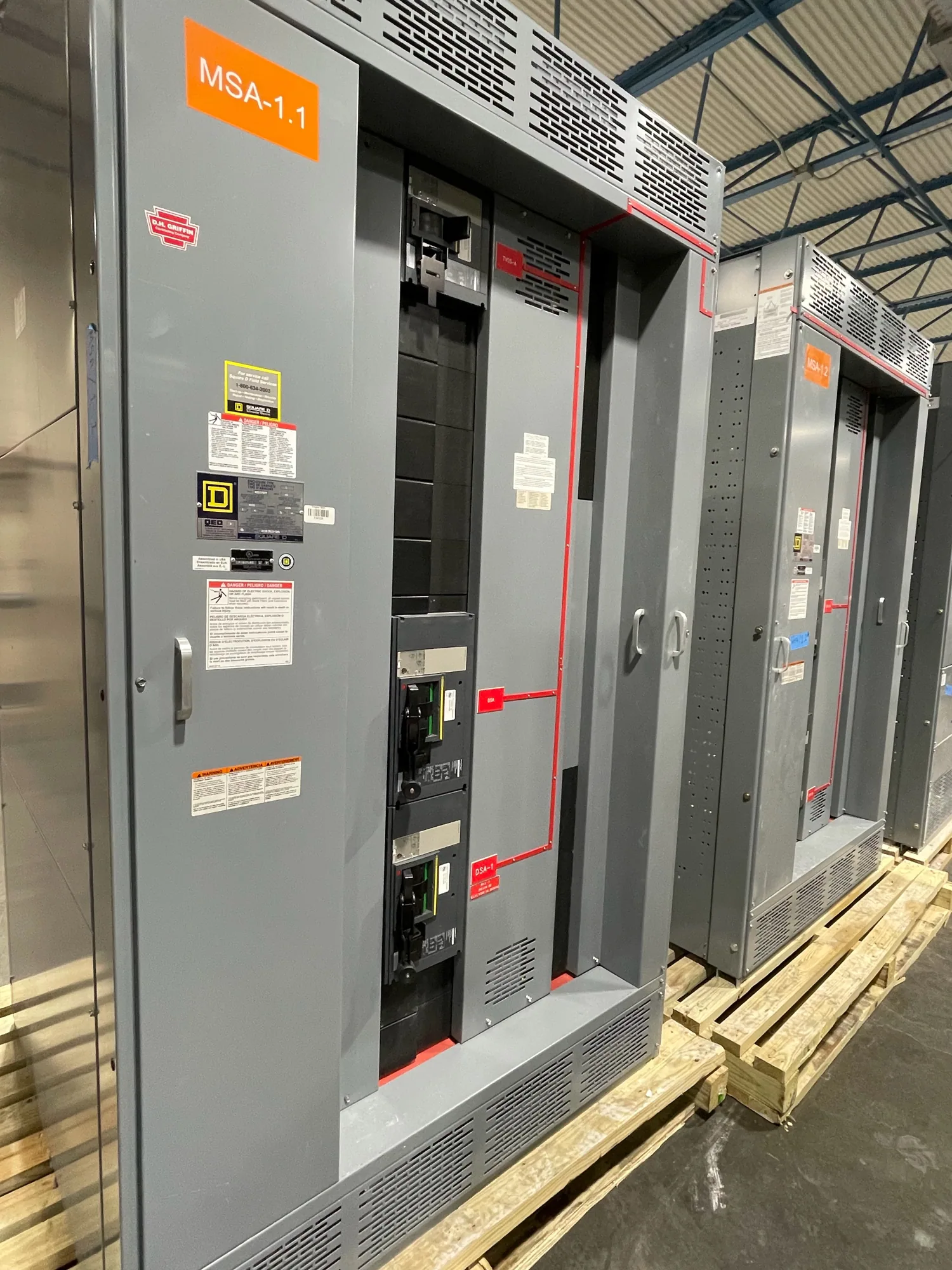
Electrical switchboards may be one interface in a low-voltage distribution design, but they are not automatically the answer for every campus system or voltage class. The specified one-line diagram, ratings, protective devices, enclosure, and connections determine the required equipment. For a new custom assembly, South Carolina Switchgear Builders can review a project specification and supply equipment built to specification. Any listing, rating, testing, availability, and delivery schedule must be confirmed for the specific design and order.
Build a reliable information package
Before requesting equipment pricing or submittals, gather the latest one-line diagrams, load and feeder schedules, source and transformer data, available fault-current information, protective-device types and settings, and study requirements. Identify what is confirmed and what remains an assumption. Include phase boundaries, existing equipment interfaces, planned future connections, and any owner requirements affecting construction, access, labeling, or documentation.
Also name the decision-makers: the owner’s facilities team, electrical engineer, construction manager, and purchasing contact. Clarify who approves device settings and study revisions, who resolves discrepancies between drawings and field information, and who accepts submittals. For equipment selection, provide the requested voltage class and ratings, configuration, environmental conditions, and connection details as specified by the engineer. A complete request helps suppliers identify missing information without substituting assumptions for design direction.
Review the plan before release
Before approving a purchase, compare the equipment proposal with the current project documents and the engineer’s coordination basis. Check that the quoted configuration reflects the intended source arrangement, feeder connections, protective-device schedule, and phase of work. Confirm which drawings and calculations are included, what information remains outstanding, and how revisions will be handled if the study or campus scope changes. Availability and actual lead times depend on the order and should be confirmed.
A useful review ends with documented agreement on system boundaries, required coordination range, assumed fault-current data, applicable standards, and responsible reviewers. Resolve open questions before manufacturing release, especially where an outage window or phased cutover depends on the equipment interface. Qualified personnel should perform installation, testing, and maintenance under the project’s applicable safety procedures. With clear engineering ownership and complete purchasing inputs, campus teams can evaluate continuity goals and protection tradeoffs on a system-wide basis.