Campus scope: one electrical system, many buildings
Higher education campuses often develop through multiple projects rather than a single construction event. Academic buildings, laboratories, residences, utility plants and renovations may have different service histories, schedules and equipment interfaces. Grounding and bonding decisions for new work should therefore be considered within the actual facility and distribution design, not treated as a standard detail that can be copied across every building.
Begin by defining the project boundary: a new building service, a feeder extension, replacement switchboard, central plant upgrade, or phased campus distribution change. Document what existing infrastructure remains and what is being added. The responsible engineer should identify the applicable service arrangement and establish how the new work relates to the campus distribution system, building electrical systems and owner requirements.
Coordinate grounding with the system design
Grounding and bonding serve related but distinct purposes. Equipment grounding provides a planned path for fault current, while bonding electrically connects conductive parts as required by the design and applicable rules. The specific conductors, connections and enclosures depend on the system, equipment configuration and project documents. Suppliers need clear requirements rather than assumptions based on another campus building or a familiar one-line diagram.
Neutral treatment is especially important to resolve at the correct point in the system. The engineer should specify whether the equipment is service equipment or downstream distribution, how the neutral is configured, and where neutral-to-ground connections are permitted or required. The answer depends on the actual service and grounding arrangement. Avoid duplicating or relocating a connection based on a generic description; have the project engineer coordinate it with the complete system design.
Plan feeders across buildings and phases
For multi-building work, identify each feeder’s source and destination, conductors and raceway assumptions, protective-device coordination responsibilities, and the grounding path shown in the design. Note whether a feeder serves a building, plant equipment, or a later phase. These details help the engineer check continuity and interfaces across project boundaries and help an equipment manufacturer configure new assemblies to the supplied specification.
Phasing creates practical constraints. A campus may need to keep adjacent facilities operating while a new distribution section is prepared, but an outage window does not change the electrical requirements. Confirm the cutover sequence, required isolation boundaries, access and staging assumptions, and who is responsible for field connections. Installation, inspection, testing and maintenance belong to qualified personnel following applicable safety procedures; no schedule should depend on energized work.
Owner standards and building-specific differences
Owner standards can make projects more consistent, but they should be checked against the building’s actual conditions and current engineering documents. Gather the campus electrical standards, approved drawing conventions, equipment schedules and any requirements for labeling, documentation or coordination. Ask the owner and engineer to identify which provisions apply to the specific project and whether any existing conditions require a documented exception.
Laboratories, central plants and general academic spaces may have different operational needs, but the equipment supplier should not infer special grounding requirements from a room name. The project team must define relevant loads, system configuration, interfaces and performance requirements. Where several buildings share a distribution source, confirm responsibility for feeder and equipment boundaries so that separate contractors and phases do not leave grounding details ambiguous.
Switchboards as one possible equipment interface
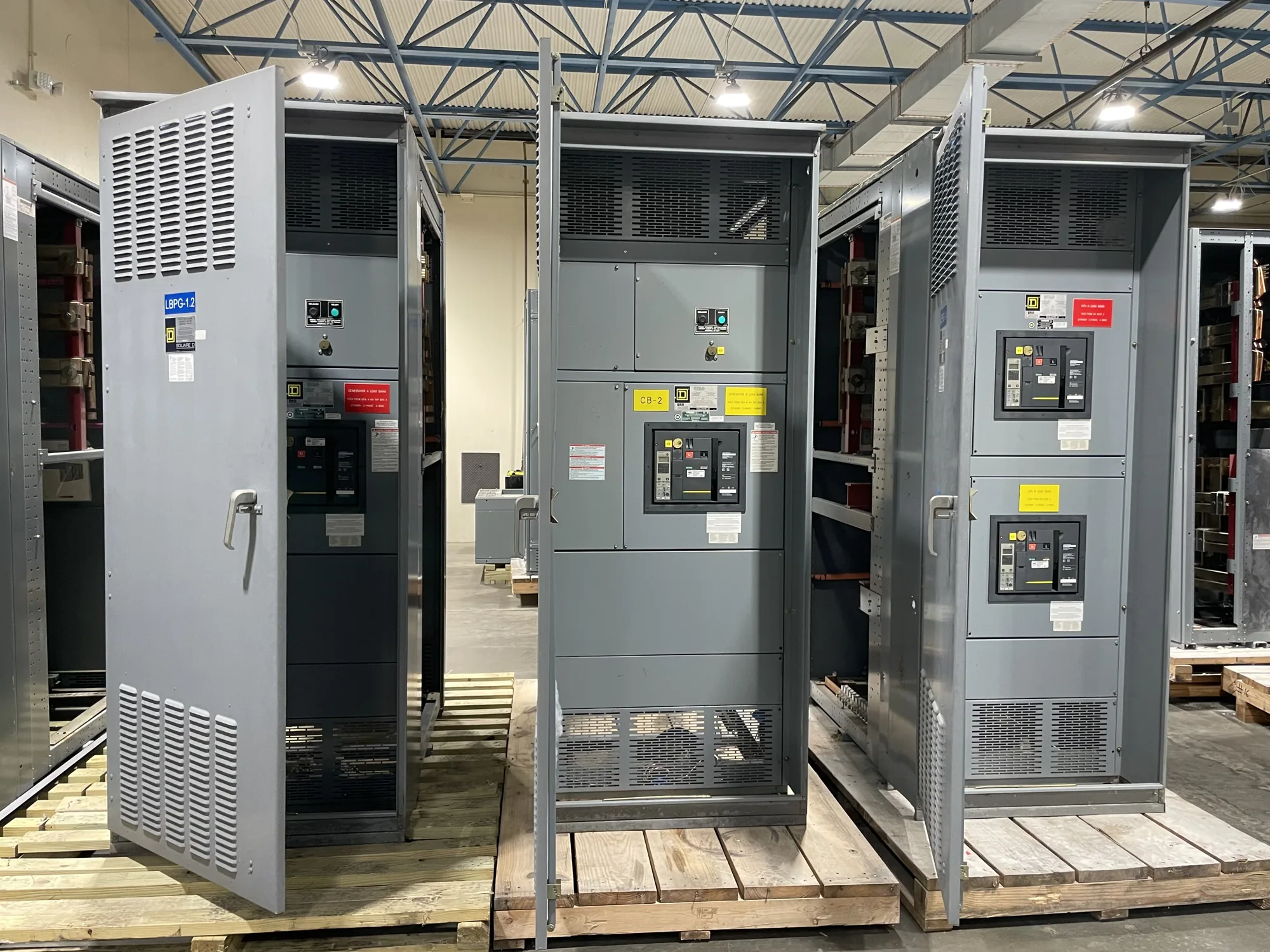
A low-voltage switchboard may be part of a campus project, but it is only one possible interface and is not automatically required for every grounding or bonding scope. If new switchboard equipment is specified, provide the one-line diagram, service and downstream designation, system details, protective-device requirements, conductor and termination information, enclosure conditions, and any project-specific grounding and neutral instructions.
South Carolina Switchgear Builders manufactures new switchboards and switchgear to specification, builds in the United States, and ships nationwide. All-American components and short lead times are available propositions, but configuration, availability and actual timing depend on the order and require confirmation. For eligible low-voltage switchboards, ask whether UL 891 applies to the specific design and whether the supplied assembly will be listed; applicability must be verified rather than assumed.
Information to resolve before requesting equipment
- Provide the current one-line diagram, equipment schedule, project location, building or phase designation, and planned procurement and outage milestones.
- State the service arrangement, voltage class, grounding method, neutral configuration, and the point at which neutral-to-ground connections are defined by the engineer.
- Identify feeder sources and destinations, required equipment interfaces, conductor and termination details, environmental conditions, and any constraints imposed by existing infrastructure.
- List applicable owner standards, codes and project specifications, while asking the responsible engineer to confirm which requirements govern this particular assembly.
- Separate confirmed requirements from open assumptions, and name the owner, engineer and contractor contacts who can resolve technical questions.
Review interfaces and coordinate the next step
Before releasing equipment information, have the owner, electrical engineer, contractor and supplier review the same design basis. Confirm who approves grounding and bonding details, who verifies field conditions, and who coordinates equipment submittals with the feeder and cutover plans. Any drawing revisions should be distributed to affected parties, especially when phased construction changes the source, destination or timing of a feeder.
A complete, coordinated specification reduces avoidable clarification during procurement and helps keep the equipment scope aligned with campus operations. Send the manufacturer the project documents and clearly identified open questions; request confirmation of the proposed configuration, applicable listing, availability and delivery schedule for the actual order. The engineer remains responsible for system design, code interpretation and field installation decisions, while the manufacturer uses approved requirements to build the new equipment.