Start with the facility’s protection objectives
Chemical processing facilities can combine utility service, transformers, process distribution, large motors, and critical control loads. Protective relay selection should begin with the electrical system’s hazards and operating objectives, not with a preferred relay model. The responsible project engineer should identify the equipment and circuits requiring protection, the fault conditions to address, and the consequences of interruptions to process and personnel safety.
Map normal and alternate power paths, significant loads, tie points, and sources that may operate in parallel. Document how operating modes change the available sources or current paths. A hypothetical motor feeder, for example, may need different consideration from a general distribution feeder, but the correct protection functions depend on the motor, circuit, upstream devices, and approved engineering study.
Relate relay functions to the protected equipment
Specify protection by function and application. Depending on the circuit and engineering analysis, functions may address overcurrent, ground-fault conditions, phase imbalance, or equipment-specific risks. The project engineer should determine what is appropriate, how each function operates, and what trip or alarm response is intended. A relay feature should not be selected solely because it appears on a standard feature list.
For each device, identify the protected zone, upstream and downstream protective devices, breaker or trip interface, and any required alarm or supervisory signals. Establish which conditions should trip equipment and which should produce an alarm or other defined response. Process operating requirements matter, but they do not replace electrical protection analysis; the owner’s operations and safety stakeholders should review the intended behavior.
Define sensing inputs and control power
Relay specifications should state the required current and voltage sensing inputs, including their source and relevant instrument-transformer information where applicable. Confirm the project’s available control power and how the relay, trip circuit, and related indications will be powered. The engineer and equipment supplier should resolve interface details against the actual breaker, switchgear, or switchboard design rather than assume that a relay can be applied interchangeably.
Also identify communications, metering, event records, remote indications, and control interfaces that the facility needs. These requirements can affect device selection, wiring, panels, and integration effort. Clarify the communication protocol and responsible system integrator if remote monitoring is planned. Confirm how loss of control power, sensor input, or communication is handled and documented for the specific design.
Coordinate settings across operating conditions
Relay settings must reflect the system study and coordination objectives, including available fault current, equipment limits, protective-device characteristics, and operating configurations. Provide the engineer with current one-line diagrams, source and transformer data, cable information, motor details, and existing or planned protective-device data. Missing or outdated inputs can undermine setting recommendations, so identify assumptions and unresolved data explicitly.
Review selectivity, clearing times, and equipment withstand as applicable to the project. Where a facility uses alternate feeds or ties, ask whether settings or coordination change by operating mode and how any changes are controlled. Final settings and acceptance criteria belong to qualified project personnel, supported by the applicable device documentation and project procedures. Do not treat factory configuration or a generic setting example as a substitute for the site-specific study.
Account for classified areas and equipment placement
Chemical processing sites may include hazardous or classified locations, but classification is facility- and area-specific. The owner’s hazardous-area documentation and responsible electrical engineer should establish where equipment may be installed and what requirements apply. Relay selection must be considered with its enclosure, wiring, control components, and installation location; a relay’s suitability cannot be inferred from its function or from the general description of a process area.
Where a location is unsuitable for the proposed assembly, evaluate equipment placement in a suitable area and define the necessary sensing, control, and communications interfaces. Confirm enclosure and environmental requirements for the actual installation, including relevant exposure and ambient conditions. These decisions should be coordinated with the facility’s hazard assessment and equipment specification; do not assume that one enclosure rating or relay arrangement fits every chemical processing application.
Coordinate the relay with new distribution equipment
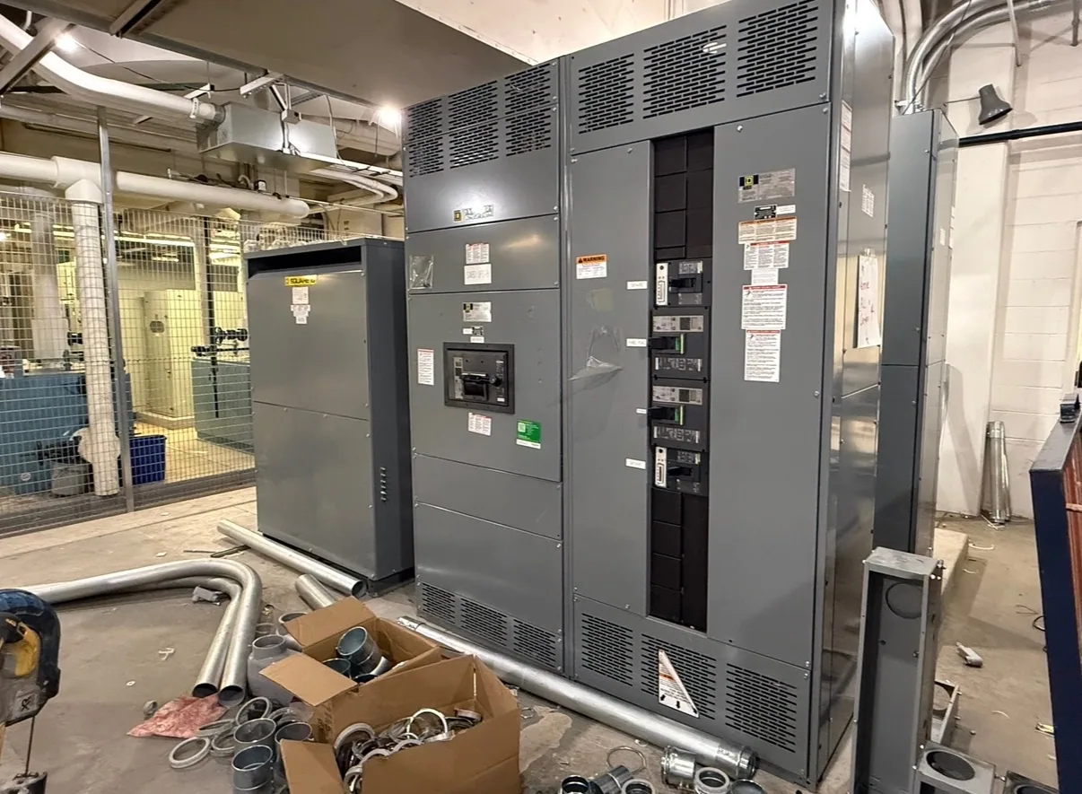
Low-voltage switchgear can be one possible interface for facility protection, but it is not automatically required for every project. Determine whether the scope calls for low-voltage switchgear, a switchboard, another assembly, or relays applied to existing equipment. If purchasing new equipment from South Carolina Switchgear Builders, provide the required functions and interfaces early so the proposed configuration can be reviewed against the project specification.
Prepare a package containing the one-line diagram, equipment schedule, system study assumptions, relay function requirements, sensing data, control-power details, communications needs, installation environment, and applicable standards. State which party supplies and verifies relays, instrument transformers, breaker interfaces, settings, testing, and integration. Availability, delivery timing, ratings, testing, and any listing or standard applicability must be confirmed for the actual configuration; do not assume every assembly has the same approvals or scope.
Use a project review before releasing the specification
Before requesting a proposal, ask the owner, electrical engineer, operations representative, and integrator to review the protection philosophy, operating modes, hazard-area boundaries, and trip and alarm responses. Record open items, design assumptions, and required submittals. Confirm who will produce and approve coordination studies and settings, and who will handle commissioning tasks under the project’s safety procedures.
A clear, coordinated specification helps the manufacturer assess the requested new equipment and identify interface questions before configuration. South Carolina Switchgear Builders manufactures US-built equipment with all-American components, custom to specification, and ships nationwide. Lead times depend on the order and must be confirmed. Final selection remains tied to the project’s engineering, documented device capabilities, installation conditions, and approved equipment scope.