Why campus-wide coordination matters
A commercial campus may combine several buildings, tenant spaces, central mechanical systems, and electrical services added in different construction phases. Grounding and bonding therefore need to be considered as part of the overall distribution design, not as an isolated equipment detail. A change to a service, feeder route, or building connection can affect how the engineer coordinates the system and its equipment interfaces.
For owners planning new switchboards or related distribution equipment, the goal is to give the design team a clear, consistent basis for procurement. Existing campus conditions, planned building additions, metering arrangements, and operational boundaries all matter. The responsible electrical engineer should establish the applicable design requirements for each part of the system and confirm that proposed equipment matches those requirements before it is released for manufacture.
Establish the system arrangement first
Start with a current one-line diagram showing the sources, service points, distribution equipment, feeders, and building connections in scope. Identify which portions are existing and which are new, and indicate planned extensions where they are sufficiently defined. The engineer should confirm the system grounding arrangement and the intended neutral treatment at each relevant point. Do not assume that a detail used in one building automatically applies to another service or phase.
Equipment grounding and bonding serve related but distinct design purposes. Equipment grounding conductors and bonding connections are coordinated with the electrical system so that exposed conductive parts and equipment enclosures are addressed according to the project design and applicable requirements. Neutral conductors have a separate role, and their treatment depends on the service and system arrangement. The design team—not a purchasing assumption—must determine where neutral-to-ground connections belong.
Account for metering, isolation, and expansion
Campus owners may need separate metering or operational boundaries for buildings, tenants, or major loads. These decisions can affect where distribution equipment is located and how incoming and outgoing circuits are organized, but they do not by themselves establish a grounding or bonding method. Ask the engineer to identify the intended service configuration, metering points, isolation needs, and responsibility boundaries, then reflect those decisions in the drawings and equipment specification.
Future growth deserves similar discipline. Planned additions, larger mechanical loads, or tenant turnover may change feeder needs and equipment arrangements. Record which future provisions are definite and which remain options; suppliers should not infer a future configuration from a general statement such as “allow for expansion.” The engineer can specify any required spaces, connection provisions, or other design features and confirm how they fit the equipment and project scope.
Coordinate equipment interfaces and construction phases
Phased construction can leave new equipment connecting to existing distribution while other portions of a campus remain in service. Before procurement, define the physical and electrical interface: source and load locations, feeder entry, enclosure and layout constraints, and the grounding and bonding details the equipment must accommodate. The project team should also identify who is responsible for field connections and how those interfaces will be documented for installation.
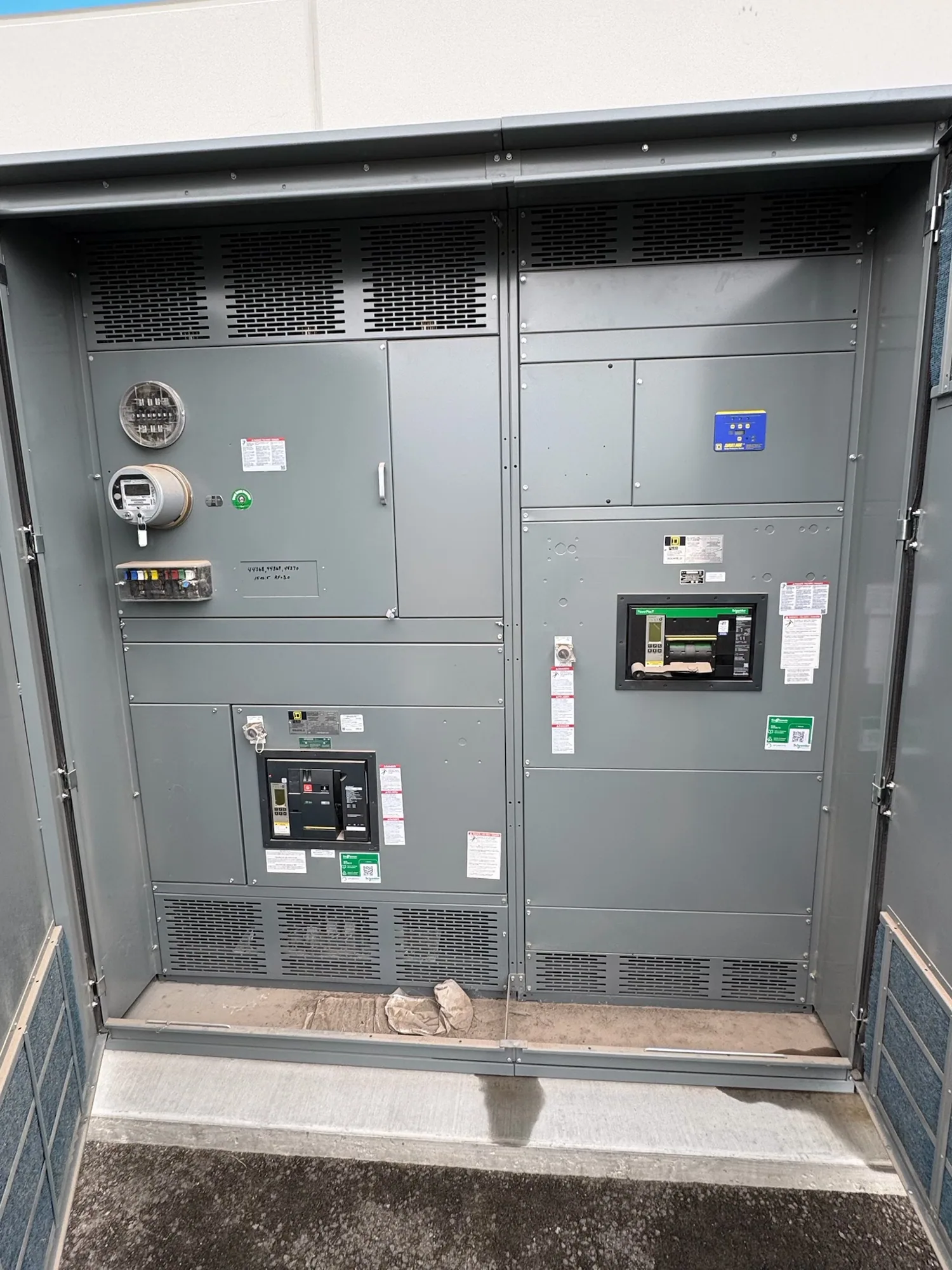
An electrical switchboard may be one interface in a low-voltage distribution design, but it is not the answer for every campus system. The selected equipment type and configuration depend on the project design. For a new switchboard, provide the supplier with the approved specification and drawings, including required ratings and any applicable listing expectations. UL 891 applies to eligible low-voltage switchboards; applicability and assembly listing must be verified for the specific design rather than presumed.
Prepare a complete equipment inquiry
A useful purchasing package includes the project location, equipment scope, system voltage and configuration, current one-line diagram, circuit or feeder schedule, required ratings, and relevant physical constraints. Include the grounding and neutral requirements established by the engineer, the intended metering and isolation arrangements, and any phase-specific boundaries. Clearly mark unresolved assumptions and identify the person authorized to answer technical questions so that bids are based on a consistent design.
Also describe the schedule and coordination milestones without treating a requested date as a confirmed delivery commitment. Equipment availability and actual lead times depend on the order and must be confirmed. New equipment can be manufactured to specification, but configuration, ratings, listing, testing, and delivery details require review against the actual project documents. Share revisions promptly and use controlled drawing review so that changes in one phase do not silently conflict with another.
Review the design before release
Before approving equipment documents, have the responsible engineer and relevant owner, facilities, and construction stakeholders check the proposed arrangement against the project basis. Confirm that neutral treatment, bonding interfaces, metering, feeder identification, and expansion provisions match the approved design. Resolve deviations in writing, and make sure scope boundaries are clear between the equipment supplied and connections or work performed elsewhere.
For an inquiry to South Carolina Switchgear Builders, submit the project-specific drawings, specification, and schedule assumptions for review. The manufacturer can use that information to evaluate new equipment requirements and clarify open items; the engineering team remains responsible for the system design and code decisions. Early, documented coordination helps align procurement with campus phasing while giving qualified installation personnel a defined basis for completing the work under applicable safety procedures.