Why campus distribution needs a coordinated view
A commercial campus may combine several buildings, tenant spaces, central mechanical systems, and services added in separate construction phases. Each area can have different operating priorities, but the distribution network connects them through upstream sources and feeders. Selective coordination planning considers how protective devices relate across that network so a fault can be isolated at the intended point, subject to the project’s design criteria and verified equipment data.
This is an engineering objective, not a promise that every disturbance will affect only one load or that the entire campus will remain energized. The responsible engineer defines the required scope, evaluates the available device combinations, and confirms applicable project and code requirements. Owners, facility staff, contractors, and equipment suppliers contribute different information; early alignment helps prevent procurement assumptions from diverging from the coordinated design.
Trace sources, feeders, and operating priorities
Start with a current one-line diagram showing utility or other sources, transformers, main distribution, building feeders, and major downstream distribution points. Identify normally open ties, alternate sources, generators, or other operating modes only where they are part of the project. A coordination study must account for the configurations that can actually be used, because changing the source or system arrangement can change the current and timing relationships under review.
Map critical and noncritical loads by building or function, and note where a feeder interruption has broader operational consequences. Include mechanical equipment, life-safety systems, tenant distribution, and shared campus services as applicable, without assuming that all loads receive the same treatment. The owner and engineer should establish priorities and boundaries: which devices and operating modes belong in the analysis, and what performance the project expects when a fault occurs.
Evaluate protective-device behavior and limits
Selective coordination depends on the time-current behavior of protective devices in series. The engineer compares device curves and relevant manufacturer data over the specified range, considering settings, tolerances, and the system’s available fault current. If device characteristics overlap or data are incomplete, coordination may not be demonstrated for the full required range. A conclusion should therefore be tied to the actual configuration and documented assumptions, not inferred from device labels alone.
There can be tradeoffs between selectivity, equipment protection, and operating requirements. A proposed setting or device choice may affect clearing time or the coordination margin; the engineer must assess those effects against the design criteria and equipment capabilities. Do not assume one breaker family, switchboard, or switchgear lineup automatically provides selective coordination. Confirm the exact devices, trip units, settings, and combinations proposed for the project.
Plan for growth, metering, and isolation
Campus service growth can change feeder sizes, transformer arrangements, and fault-current conditions. Ask whether planned tenant additions, new mechanical loads, or future building connections should be included now, and clearly distinguish firm project scope from conceptual allowances. Spare space or future provisions do not establish that a later expansion will coordinate with the original system; changes may require updated calculations and review of the installed configuration.
Metering and isolation also affect practical layout and phasing. Define where energy measurement is needed, which parties require access to readings, and how maintenance or construction boundaries should be arranged. These requirements may influence distribution sections and feeder organization, but must be reconciled with the engineer’s protection design. For phased work, document temporary and final source arrangements, planned cutovers, and the party responsible for approving each configuration before equipment is ordered or connected.
Choose equipment around the engineered interface
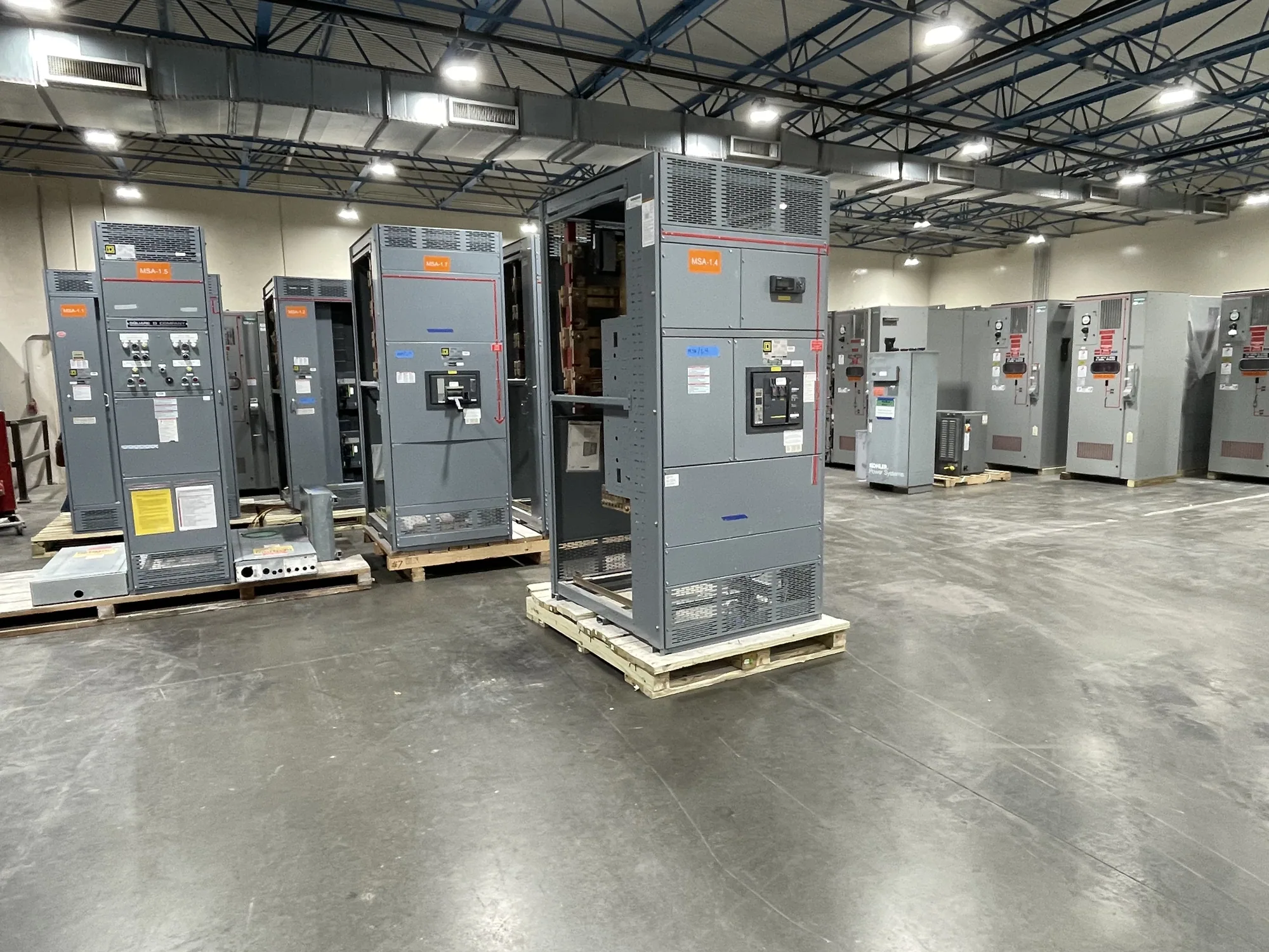
Low-voltage switchgear may serve as one interface in a campus distribution system, but it is not automatically required for every project. The selection depends on system requirements, available fault current, specified ratings, device coordination, metering, space, access, and the project’s construction plan. A new custom assembly should be developed from the approved design documents and confirmed requirements rather than used to resolve missing engineering decisions during procurement.
When requesting a proposal from South Carolina Switchgear Builders, provide the applicable one-line diagram, equipment schedules, project specifications, device and trip-unit requirements, metering needs, and enclosure or installation constraints. Include the requested coordination-study scope and identify who will supply final settings and approve submittals. The manufacturer builds new equipment to specification; assembly details, ratings, listing applicability, testing, availability, and delivery timing must be confirmed for the specific design and order.
Coordinate submittals, phasing, and review
Before release, align the owner’s operating priorities, engineer’s calculations, contractor’s installation plan, and supplier’s equipment submittals. Review assumptions about sources, tie positions, device settings, and future provisions against the latest documents. If the design changes, such as a revised feeder or transformer, route the change to the responsible engineer for evaluation; procurement drawings should not silently substitute for a coordination study.
For phased construction, establish which drawings and settings govern each stage and how changes will be recorded. Qualified personnel must perform installation, testing, and maintenance under applicable safety procedures; planning documents are not authorization for energized work. A clear review path helps campus stakeholders understand what has been specified, what remains to be confirmed, and how the final equipment fits the approved distribution design.
Prepare a focused campus coordination checklist
Before seeking equipment pricing, assemble the current one-line diagram, load and building schedule, source configurations, available fault-current information, and the engineer’s coordination criteria. Identify metering points, isolation boundaries, phasing milestones, anticipated growth, and any required equipment ratings or standards. Mark unresolved values as open engineering items rather than treating estimates as final inputs, and state which project documents take precedence if they differ.
Then assign reviewers: owner or facility representative for operating priorities, engineer for protection and compliance decisions, contractor for installation and phasing constraints, and supplier for equipment fit and submittal coordination. Ask which data are needed to complete the proposal and when design changes require renewed review. With those responsibilities clear, the campus team can evaluate new distribution equipment against the intended system behavior and carry a consistent basis from design through procurement.