Define the protection scope across the facility
Data center relay selection begins with the power system, not a standalone device. A facility may receive utility power, use generators or other backup sources, and distribute energy through multiple paths to IT and cooling loads. The actual arrangement depends on the project. The owner’s engineer should identify each source, normal and alternate operating states, transfer points, major distribution equipment, and the boundaries of the protection study.
High-density IT loads and essential cooling can make continuity objectives important, but relay decisions must follow the documented system design. Redundancy labels alone do not establish how protection should operate during a fault, maintenance condition, or source transfer. Define which loads are served in each mode, what equipment can be isolated, and which switching actions are automatic or operator-directed. These assumptions give the engineer and equipment suppliers a shared basis for reviewing the protection scheme.
Match relay functions to the system study
Protective functions should be selected from the project’s fault analysis, equipment characteristics, operating modes, and protection objectives. Depending on the application, the engineer may consider overcurrent, ground-fault, voltage, frequency, directional, or other functions. This is not a universal relay feature list: a function is useful only where its sensing inputs, logic, settings, and trip path suit the specific circuit and documented study.
Coordination across utility sources, generators, transformers, and downstream distribution requires particular care when sources operate in different combinations. Fault current and direction can change with the configuration, so settings suitable for one mode may not suit another. The responsible engineer should assess applicable scenarios and determine whether approved setting groups, interlocking, or other design measures are needed. Suppliers need the final functional requirements and interfaces; they should not be expected to invent protection settings without engineering direction.
Specify sensing, control power, and trip interfaces
A relay’s application depends on more than its catalog functions. Identify the required current and voltage sensing sources, their locations and ratios where applicable, wiring responsibilities, and the devices each relay must monitor or trip. Confirm the control-power source and its behavior during the events the protection scheme is intended to address. These details affect equipment design, drawings, commissioning plans, and the division of work among the engineer, switchgear manufacturer, controls integrator, and installer.
Also document communications and status needs. If operators need alarms, event records, or data presented through a facility monitoring system, define required points, protocols, time synchronization expectations, and ownership of configuration. Do not assume that a relay automatically provides a complete monitoring solution or that a supplier’s standard arrangement matches the facility platform. Confirm which signals are essential for safe operation and troubleshooting, and distinguish them from optional monitoring features.
Plan for phased capacity and maintainability
Data center capacity may be installed in stages, while later work connects new distribution or load blocks to an operating system. The project team should identify each planned phase, the equipment included, temporary operating arrangements, and the future interfaces that need to be reserved. Protection settings and coordination studies should address the intended configurations, with assumptions recorded so later expansions can be reviewed rather than relying on undocumented carryover.
Maintainability also deserves explicit treatment. Ask how qualified personnel will identify protective devices, access approved settings information, review event records, and perform required inspection or testing under applicable safety procedures. Consider whether device replacement, control-power isolation, or communications maintenance affects other protection functions. These are design and operating questions for the responsible engineer and owner; they should be resolved in drawings, procedures, and supplier submittals before equipment is released.
Resolve trade-offs before equipment procurement
Protection sensitivity, selectivity, simplicity, and resilience can pull design choices in different directions. A scheme intended to isolate only the affected section may require additional sensing, logic, or coordination review. More functionality can also mean more configuration and lifecycle documentation. The project engineer should explain the chosen balance and identify any operating modes where selectivity, backup protection, or continuity objectives are limited by the system design.
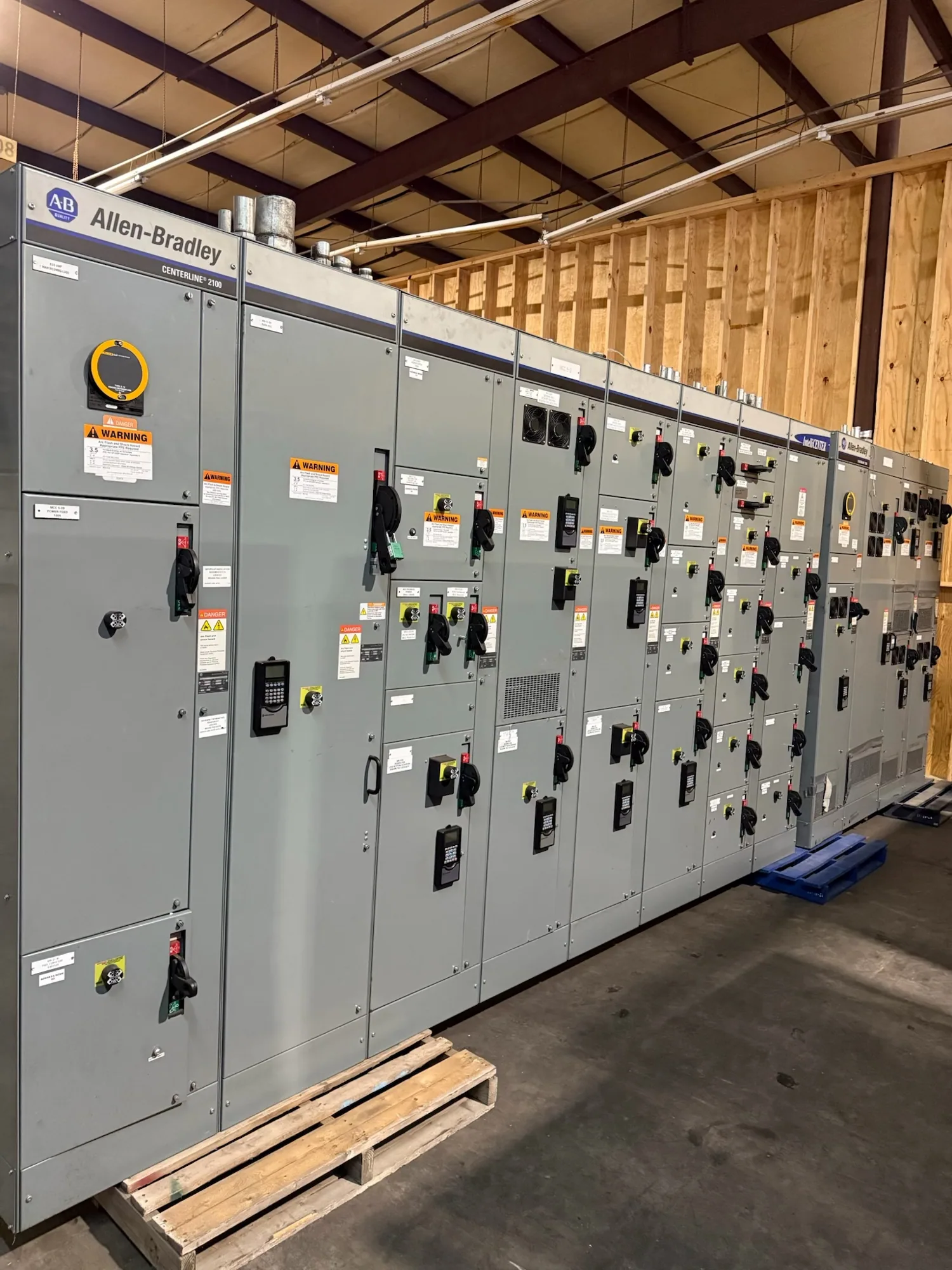
Low-voltage switchgear can be one interface in a data center distribution system, but it is not automatically required for every project or every relay application. If new switchgear or switchboards are being specified, provide the equipment scope, one-line diagram, electrical ratings, protection functions, sensing requirements, trip interfaces, communication needs, and required submittals. South Carolina Switchgear Builders manufactures new equipment custom to specification, with US-built equipment and all-American components; configuration and applicability must be confirmed against the project documents.
Prepare a coordinated project information package
Before requesting equipment pricing or submittal review, assemble the current one-line diagram, load and source information, operating sequences, protection study criteria, and a list of required functions and interfaces. State which documents are preliminary and which are approved for design. Include planned expansion phases, environmental or installation constraints relevant to the equipment, the desired monitoring points, and the parties responsible for settings, wiring, integration, and commissioning.
Ask the engineer to identify applicable standards and confirm the requirements for each specific assembly; applicability, ratings, listing, and testing are design-dependent and must be verified. Review supplier drawings and exceptions with the owner, engineer, and controls stakeholders before approval. Actual availability and lead times depend on the order and require confirmation, as do delivery dates and the supplied configuration. A complete, reviewed specification lets the manufacturer identify open questions early and coordinate new equipment with the facility’s protection and operating plan.