Define the system and continuity goals
Selective coordination planning starts with the facility’s power-system boundaries, not a single switchgear lineup. A data center may have high-density IT loads, cooling equipment, redundant distribution paths, backup sources, and multiple operating modes. The owner and responsible engineers should define which loads need continuity, which faults must be isolated, and how the system is expected to operate during normal, maintenance, and alternate-source conditions.
Map the power path from each source through distribution equipment to the relevant loads. Include utility service, generators, transfer equipment, transformers, switchboards, panelboards, and downstream protective devices where applicable. The actual architecture varies by project. A one-line diagram should identify normal and alternate connections, tie positions, planned future sections, and any operating restrictions that affect coordination decisions.
Coordinate protective devices across operating modes
Selective coordination concerns how upstream and downstream overcurrent protective devices respond to fault current. The design team evaluates time-current behavior so that, where required by the project, the device nearest a fault operates without unnecessarily interrupting unaffected portions of the system. Coordination is not established by choosing a product category alone; it depends on device characteristics, system configuration, available fault current, and the specified operating conditions.
Data centers can present several source and configuration cases. Utility and generator sources may produce different fault-current conditions, while open or closed ties and maintenance arrangements can change current paths. Engineers should identify the cases that require analysis and verify whether proposed settings and devices support the required coordination in each. Any exceptions, limitations, or intentional tradeoffs should be documented for owner and engineering review.
Continuity and protection must be considered together. Longer clearing times or different settings may affect equipment withstand, arc-flash analysis, and the protection objectives established for the facility. Do not treat a coordination target as permission to compromise equipment protection. The responsible engineer should assess applicable project requirements, device capabilities, system studies, and safety procedures before approving settings or a final arrangement.
Plan capacity phases and future changes
Phased capacity additions are common planning considerations, but future growth should be described precisely rather than assumed. Identify the initial and anticipated load blocks, equipment spaces or sections intended for later work, and the conditions under which new sources or distribution paths may be added. Ask the engineer to state which future assumptions are included in the present coordination study and which will require renewed analysis.
A planned addition can change fault current, loading, device selection, and coordination relationships elsewhere in the system. Specify whether future equipment is part of the current purchase or only a design allowance. Suppliers need clear boundaries: the required scope, interfaces, physical arrangement, ratings, and any project-defined provisions. Changes to system topology or protective-device settings should be reviewed by qualified project personnel before implementation.
Specify monitoring and maintainability needs
Monitoring requirements should follow operational questions. Determine which electrical quantities, alarms, device status points, or communications interfaces the owner expects to observe, and identify where those signals must be available. Specify protocols or integration requirements only when established by the project team. The equipment supplier needs to know whether monitoring components, wiring provisions, or defined interfaces belong in the equipment scope.
Maintainability also affects how a system is specified. Clarify access expectations, isolation methods, maintenance procedures, and whether the design anticipates work on one section while other paths remain in service. Do not assume that redundancy alone makes maintenance safe or uninterrupted. Qualified personnel must plan and perform installation, testing, and maintenance under applicable safety procedures, using project-approved methods and equipment information.
Choose equipment by its defined role
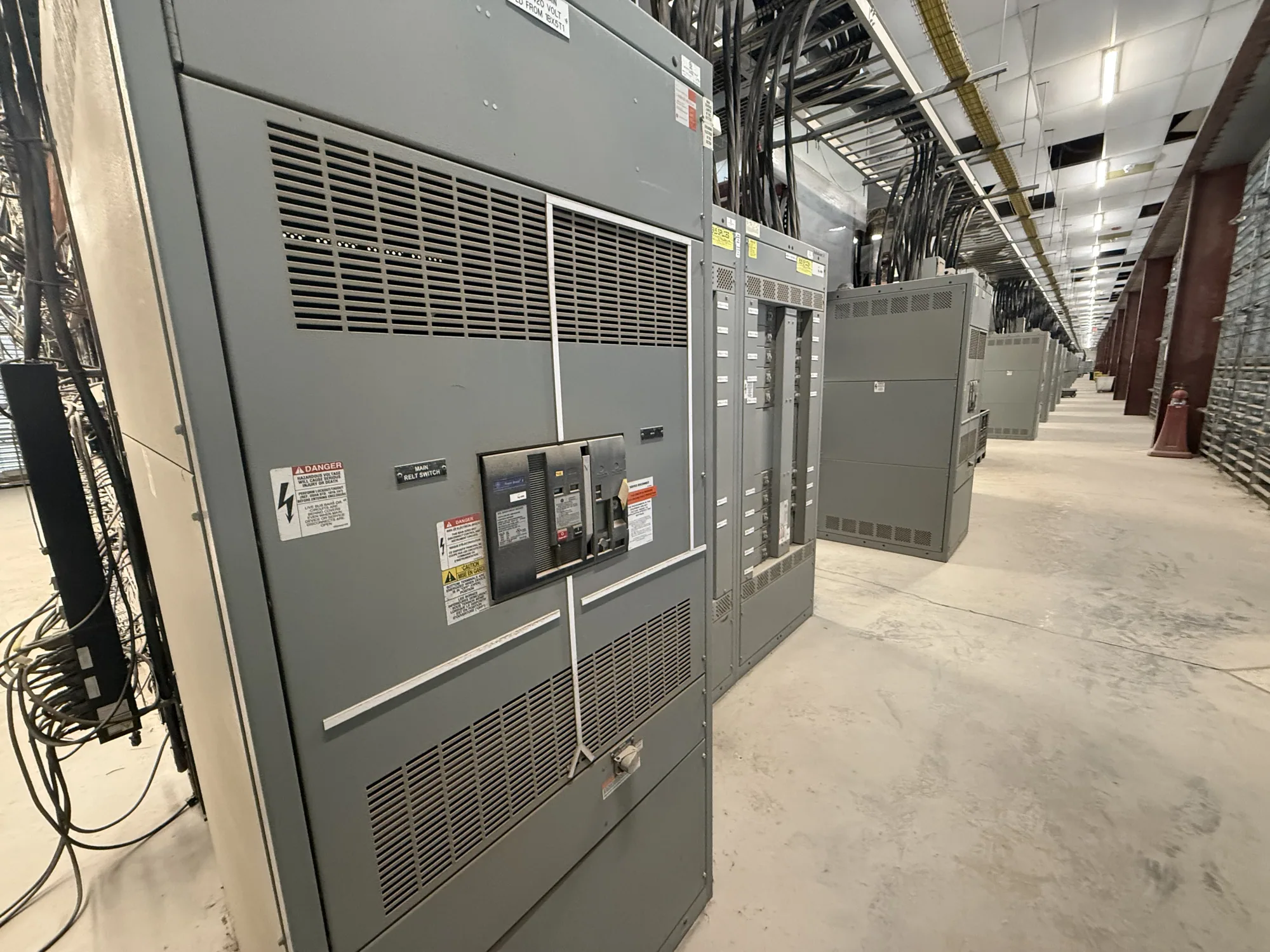
Low-voltage switchgear may be one interface in a data center distribution system, but it is not automatically required for every project. The design may use different equipment types at different points. Specify the equipment’s function, voltage class, bus and feeder arrangement, source connections, protective-device requirements, and interfaces with adjacent equipment. Confirm ratings and construction details against the actual one-line diagram and project specification.
For new equipment, provide the manufacturer with the current drawings and a clear scope of supply. Include available fault-current information, source and tie operating cases, load and phasing assumptions, device requirements, monitoring points, environmental conditions, and required project submittals. Identify applicable standards and any listing requirements for the specific assembly, for the responsible engineer and manufacturer to verify. Applicability depends on the particular design; do not assume a standard or listing applies to every assembly.
Prepare a coordinated purchasing and review package
Before requesting a quotation, reconcile the one-line diagram, equipment schedule, written specification, and coordination-study assumptions. Flag unresolved items rather than allowing a supplier to infer them. State who is responsible for device selection, settings, study completion, drawing approval, and field integration. A clear responsibility matrix helps distinguish equipment supply from engineering decisions and work performed by other project participants.
Review proposed drawings and submittals with the owner, electrical engineer, operations team, and other affected stakeholders. Check that source configurations, protective-device information, interfaces, monitoring provisions, and future phases align with the approved design. Confirm project-specific ratings, availability, applicable listing or testing requirements, and delivery dates against the actual order. This disciplined review gives the manufacturer the information needed to quote new equipment accurately and helps the project team carry coordination intent from design through procurement and installation.