Start with the facility and its operating conditions
Grounding and bonding decisions in a food and beverage facility connect the electrical distribution system to the equipment and spaces it serves. A hypothetical plant may combine process motors, refrigeration compressors, packaging lines, pumps, and washdown areas. These loads can have different operating patterns and environmental exposures, so the responsible engineer should evaluate the facility as a coordinated system rather than relying on a single equipment detail.
Begin with the one-line diagram, service arrangement, equipment locations, and process requirements. Identify which areas are routinely washed, where moisture or cleaning agents may reach electrical equipment, and how production equipment connects to feeders and branch circuits. The owner, electrical engineer, equipment manufacturers, and installation team should agree on the design basis before new distribution equipment is specified. Site conditions and process changes can affect both equipment selection and installation details.
Coordinate grounding, bonding, and neutral treatment
Equipment grounding provides a fault-current path as part of the system design; bonding connects conductive parts as required for the installation. The project engineer must determine the applicable arrangement for service equipment, feeders, separately derived systems, and downstream equipment. Neutral-to-ground connections, grounding-electrode connections, and bonding locations depend on the actual system and applicable code. Do not assume the same treatment applies at every panel or machine.
For each source and distribution point, document the system configuration and identify who is responsible for grounding and bonding connections in the field. Confirm how conductors, enclosures, raceways, and connected equipment are addressed in the approved design. If a process machine or packaged skid has its own electrical interface, its drawings and manufacturer instructions should be reviewed alongside the facility one-line. Clear boundaries help prevent missing connections or unintended duplicate neutral-ground bonds.
Account for washdown, sanitation, and equipment location
Washdown exposure is a design input, not a reason to assume a particular enclosure or construction detail. The engineer should describe the location, cleaning method, likely exposure, ambient conditions, and any applicable owner criteria. Confirm that the specified equipment configuration is suitable for those conditions, including the enclosure, entry points, finish, and installation orientation where relevant. Actual environmental suitability must be established for the specific assembly and site.
Sanitation procedures may shape equipment placement and access, while production continuity can affect how distribution sections and control interfaces are arranged. Discuss where operators and maintenance staff need clearance, how cable routes avoid process conflicts, and whether equipment is separated from direct spray or corrosive exposure. These decisions should be coordinated with facility, sanitation, and electrical stakeholders; a switchboard or switchgear specification alone cannot resolve every site-interface concern.
Consider motors, drives, and continuity together
Refrigeration and process motors can introduce starting, operating, and control requirements that influence distribution planning. Provide motor and drive data, operating sequences, expected simultaneous loads, and any known sensitivity of controls or instrumentation. The responsible engineer can use that information to evaluate system coordination and identify design questions. Do not infer a grounding method or equipment rating from the presence of motors; those choices depend on the complete electrical design.
Continuity goals also deserve explicit discussion. Identify which processes may tolerate an outage, which require planned isolation, and whether future expansion or maintenance access affects the distribution layout. The project team can then review equipment grouping, feeder routing, and interface responsibilities against operational priorities. Any protective-device coordination, arc-flash assessment, or other study requirement should be established by the project’s qualified engineering team and reflected in the procurement documents where applicable.
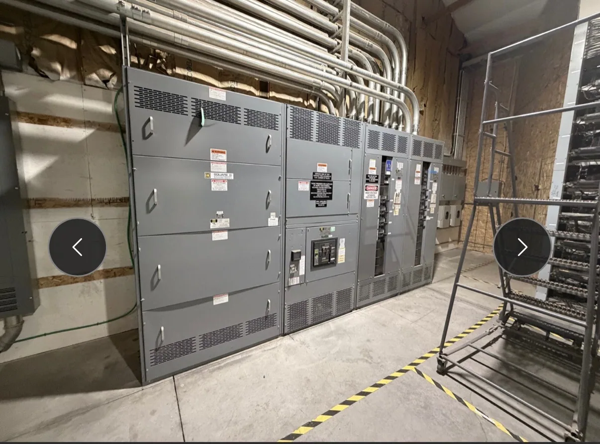
Use switchboards as one possible distribution interface
An electrical switchboard may be appropriate for some low-voltage distribution arrangements, but it is not automatically the right solution for every food and beverage facility. Selection depends on the service and distribution design, available space, load requirements, environmental conditions, and project specifications. For a new switchboard, clarify the applicable voltage class, incoming and outgoing connections, protective devices, metering or controls, and required field interfaces.
Ask the manufacturer to confirm the proposed assembly against the project specification, including ratings, construction, listing applicability, and environmental details. UL 891 applies to eligible low-voltage switchboards; whether it applies and whether a particular assembly is listed must be verified for that design. Do not apply that standard to medium-voltage switchgear. South Carolina Switchgear Builders manufactures new equipment to specification; availability and actual lead times depend on the order and must be confirmed.
Prepare a useful specification and purchase package
Before requesting a quotation, assemble the latest one-line diagram, load information, equipment schedule, site conditions, and sequence or operating notes. Identify the service arrangement, system grounding assumptions, required equipment functions, physical constraints, and known future provisions. Mark open items rather than treating uncertain details as settled. A complete package helps the manufacturer identify questions early and reduces the risk of designing around conflicting assumptions.
Include applicable codes and standards as directed by the project engineer, along with required documentation, review milestones, and the responsible parties for field connections. Coordinate submittal review with the electrical engineer, facility owner, process-equipment suppliers, and installation contractor. Confirm delivery expectations against the actual order and project schedule; do not rely on an unverified lead-time assumption. A clear, reviewed specification gives the team a sound basis for procuring new distribution equipment and coordinating it with the facility’s grounding and bonding design.