Plan across the healthcare electrical system
Grounding and bonding in a hospital are system-level design matters, not details to settle by selecting a switchboard alone. A facility may include normal and alternate power sources, essential electrical system branches, clinical areas, support spaces, and several distribution points. The project engineer must coordinate how these parts are arranged and identify which requirements apply to each portion of the installation.
Early planning should bring the owner, electrical engineer, facilities team, and equipment suppliers into a shared discussion. The design basis should identify the project scope, anticipated loads, source configuration, distribution boundaries, and applicable code and standards. New distribution equipment can then be specified against that basis, rather than relying on assumptions carried over from a different building or system.
Coordinate grounding and bonding details
Equipment grounding and bonding have related but distinct roles in an electrical system. The project documents should define the intended grounding path, bonding connections, and interfaces at service equipment and downstream distribution equipment. The responsible engineer should determine which components and enclosures require bonding and how continuity is maintained through the complete installation.
Neutral treatment depends on the actual source and system arrangement. For example, the design may need to address where neutral-to-ground connections are permitted or required, how separately derived sources are handled, and what is expected at transfer equipment. These are not universal equipment settings: the engineer must establish the scheme from the project’s source configuration and applicable requirements, then communicate it clearly in drawings and specifications.
Account for essential power and coordination
Healthcare facilities may use multiple sources and essential-system distribution to support designated loads. The project team should identify which loads belong to each branch, how sources connect, and what equipment is responsible for switching or distributing power. Grounding and bonding details must remain consistent across those interfaces, including the treatment of equipment supplied from alternate sources.
Selective coordination should be addressed where required by the project and applicable rules. It involves evaluating protective-device relationships across the system, not simply choosing a panel or switchboard in isolation. The engineer should define the study assumptions and required documentation, while equipment suppliers receive the confirmed device, fault-current, and coordination information needed for their scope. A design tradeoff may involve balancing maintainability, equipment arrangement, and the intended continuity of service.
Consider distribution equipment as one interface
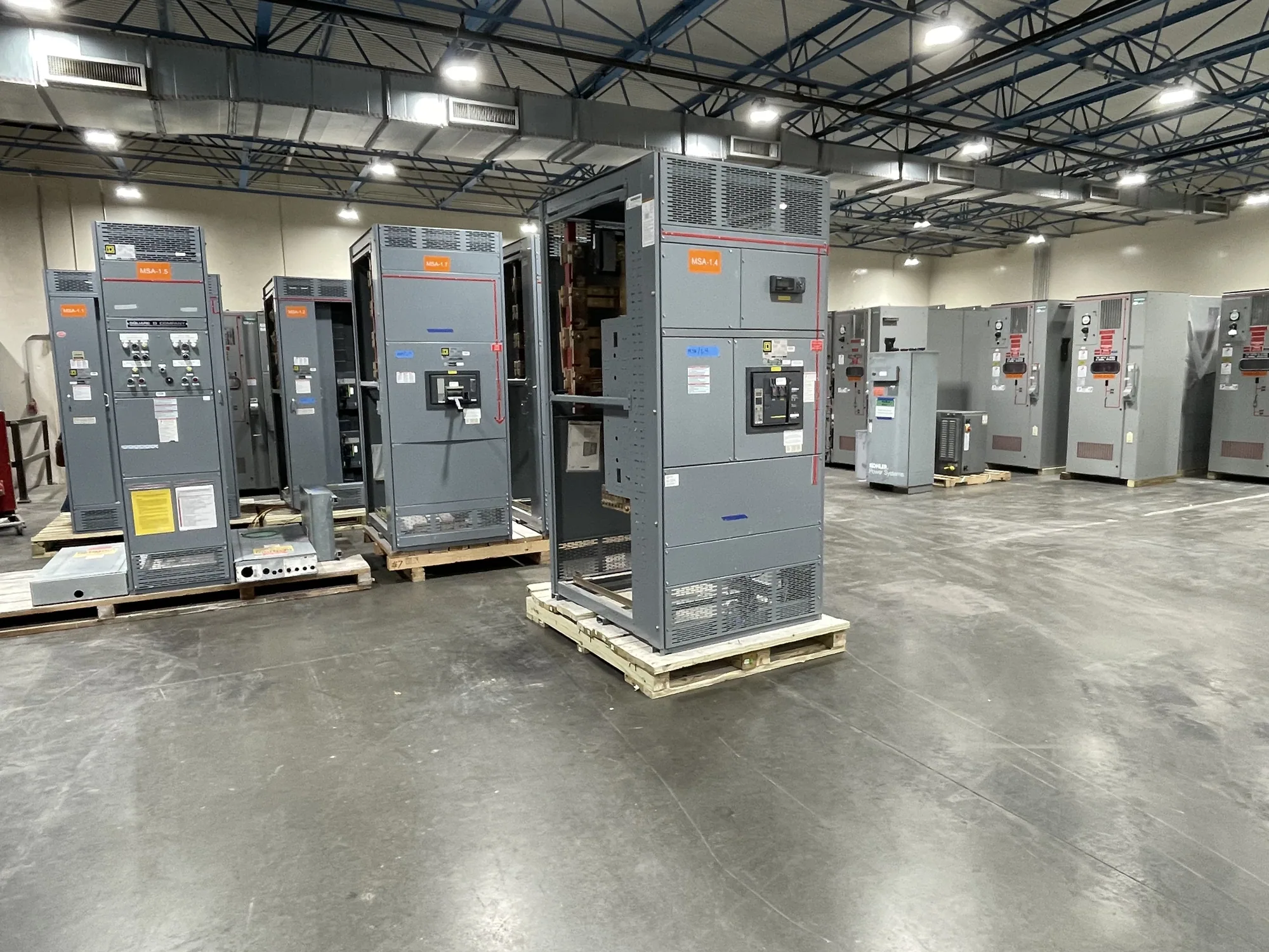
Electrical switchboards can be an interface between sources, feeders, and downstream distribution, but they are not automatically the right answer for every healthcare application. The equipment type and arrangement depend on the electrical design, required functions, available space, and project specification. Where a new switchboard is part of the scope, its grounding and bonding provisions should match the engineer’s documented system intent.
Before requesting a manufacturer’s proposal, provide the one-line diagram, equipment schedule, system voltage and phase information, source details, incoming and outgoing feeder requirements, and specified protective-device information. Include enclosure and installation constraints, neutral requirements, grounding and bonding notes, and any required documentation or project-specific testing. Identify unresolved assumptions explicitly; a supplier cannot responsibly infer design decisions from the facility type alone.
Review safety and continuity assumptions
Continuity planning should cover how the system is expected to operate during normal conditions, source transfers, maintenance, and planned interruptions. The owner and engineer should define the operational priorities and any constraints on sequencing or access. A new equipment specification can describe the required interfaces and functions, but it cannot replace facility procedures, the engineered design, or review of the complete electrical system.
Installation, inspection, testing, and maintenance must be planned by qualified personnel using the applicable safety procedures. Project documents should state who is responsible for field verification and how deviations are reviewed before they affect the installation. Keeping those responsibilities clear supports safer coordination without assuming that any particular grounding arrangement, test outcome, or continuity result is automatic.
Prepare a useful equipment specification
Before releasing a purchase request, assemble the design information into a coordinated package. Confirm the applicable codes and standards with the project engineer, identify the equipment boundary, and distinguish firm requirements from items awaiting review. Ask stakeholders to check source and neutral arrangements, bonding interfaces, protective-device coordination where required, and compatibility with the facility’s operating plan.
- Provide current drawings, schedules, and the intended normal and alternate source configuration.
- State grounding, bonding, and neutral requirements at each relevant equipment interface.
- Identify required ratings, protective devices, enclosure conditions, and project documentation for engineering confirmation.
- List open decisions, review owners, and the approval point before fabrication.
South Carolina Switchgear Builders manufactures new equipment to specification, with US-built construction and all-American components, and ships nationwide. Availability and lead times depend on the order and must be confirmed. A complete, engineer-reviewed package gives the manufacturer a sound basis to evaluate the requested configuration and coordinate equipment details with the project team before the order proceeds.