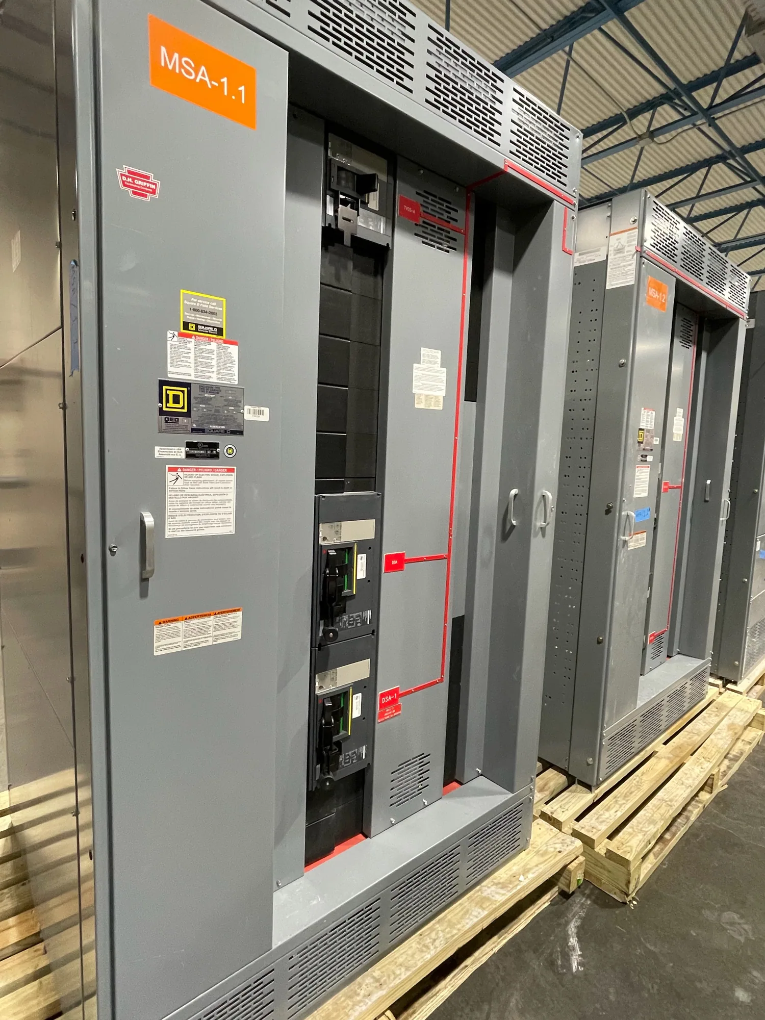
Start with the facility’s electrical functions
Hospitals and other healthcare facilities depend on coordinated electrical systems serving clinical, life-safety, operational, and support functions. Instrumentation and communications planning should begin with the project’s engineered system design—not with a generic list of switchgear features. Identify which equipment is in scope, how normal and alternate sources are arranged, and what information operators need to understand system status and respond under approved procedures.
Essential electrical system requirements are project-specific. The responsible engineer should establish the applicable system arrangement, load classifications, transfer and operating sequences, and required coordination. Equipment monitoring can support visibility, but it does not replace the engineered protection scheme, operating procedures, or qualified personnel. A supplier’s proposed points and interfaces should be checked against the one-line diagram, control narrative, specifications, and facility monitoring architecture.
Build a useful, bounded point list
A point list turns operational needs into a reviewable equipment scope. Depending on the specified design, it may identify source availability, breaker position, trip indication, alarms, metering values, or control-device status. For each point, state its source device, intended destination, signal type, naming convention, and whether it is informational or part of a defined control sequence. Confirm which points are required at the equipment and which are supplied by other systems.
More points do not automatically create better oversight. Unnecessary duplication can complicate commissioning, alarm response, documentation, and future changes. Distinguish values needed for routine situational awareness from alarms that require a defined operator response. Confirm units, scaling, thresholds, time behavior, and whether values are instantaneous or accumulated where applicable. The engineer and owner should approve the final list before it is used to configure or price new equipment.
Define communications interfaces and responsibility
Specify the required protocol, physical interface, network connection, data map, and any hardwired contacts or analog signals. A protocol name alone is not a complete interface definition: suppliers and integrators also need to know which device provides each value, how it is addressed, and what information is expected at the receiving system. The project documents should assign responsibility for furnishing, configuring, testing, and documenting each connection.
Set cybersecurity boundaries with the facility’s information technology and controls stakeholders. Clarify whether switchgear devices connect to a dedicated operational network, what access is permitted, who manages credentials, and how remote access is handled or prohibited. Confirm network ownership, approved hardware, segmentation expectations, and change control with the responsible parties. Do not assume a communications feature is approved simply because it is available on an equipment device.
Coordinate protection, continuity, and safe operation
Selective coordination should be addressed where required by the project design and applicable requirements. The responsible engineer must evaluate protective-device selections and settings in the context of the complete system, including source configurations and downstream equipment. Communications and metering do not establish coordination. Provide the engineer with accurate equipment data and clearly identify assumptions that remain open for review before the specified assembly is finalized.
Continuity planning likewise needs to reflect the facility’s approved operating strategy. Identify what monitoring is needed during normal and alternate-source operation, which alarms matter during transitions, and who receives them. Avoid treating remote indications as permission to operate equipment remotely; control functions, if specified, require explicit engineering, review, and acceptance. Installation, testing, and maintenance should be performed by qualified personnel using applicable safety procedures, with the facility’s operational constraints coordinated in advance.
Consider the service entrance as one interface
Service-entrance switchgear can be an important boundary in some projects, but it is not automatically the right scope for every healthcare facility. Where it is included, define how its metering and status information relate to utility-facing equipment, downstream distribution, and the facility monitoring system. The responsible engineer should confirm the applicable arrangement, ratings, interface requirements, and responsibility split for the actual project.
Trace each requested signal across the full path: the device producing it, the switchgear terminal or network interface, any gateway or integrator, and the destination display or alarm. Identify who supplies interconnecting wiring and network components, and who verifies end-to-end operation. This prevents gaps where each party assumes another will map, configure, or validate a point. The equipment supplier can address its defined scope when the interface and acceptance expectations are documented.
Prepare the specification and purchasing package
Before requesting a proposal for new switchgear, assemble the current one-line diagram, equipment schedules, control narrative, point list, network requirements, and relevant sections of the project specification. State the equipment type and application, required electrical data, environmental conditions, and any project-specific listing or testing requirements for confirmation. Identify which requirements are mandatory, which are preferred, and which remain subject to engineering approval.
Include stakeholder review from the owner, electrical engineer, facility operations, controls integrator, information technology, and other parties responsible for acceptance. Ask suppliers to identify exceptions, assumptions, included interfaces, exclusions, and information needed to complete the design. Confirm that proposed documentation covers the agreed point list and interface details. For applicable low-voltage switchboard assemblies, any UL 891 applicability and listing must be verified for the specific design; do not assume it applies to all equipment.
Coordinate submittals through acceptance
Use the submittal process to resolve open technical decisions before fabrication: point mapping, device selections, communication settings, naming, and division of work. Confirm availability and actual lead times against the order, since they depend on the specified equipment and project requirements. South Carolina Switchgear Builders manufactures new equipment to specification, with US-built, all-American components and nationwide shipping; project configuration and delivery details require confirmation.
For acceptance, agree in advance on which documents, inspections, and functional checks are required and who performs them. Keep the approved point list, network details, settings, and final equipment documentation aligned as revisions occur. A well-defined interface gives the facility and its project team a clear basis for integration, commissioning, and future maintenance—without substituting communications for sound engineering or safe operating practices.