Why coordination matters in regulated operations
Pharmaceutical and biotech facilities can combine process equipment, controlled environments, laboratory functions, and essential building services. A protective-device operation may affect only one branch circuit—or interrupt a broader portion of the distribution system—depending on the fault location and the devices selected. Selective coordination planning aims to limit an interruption to the affected part of the system where the specified design and protective-device behavior support that outcome.
Coordination is not a general promise that every fault will be isolated without affecting other loads. The responsible engineer defines the system boundaries, operating scenarios, and applicable requirements. Owners should identify which loads, processes, and environmental controls have continuity priorities, and what shutdown or recovery conditions are acceptable. Those priorities inform the design review; they do not replace protection, safety, or equipment requirements.
Define the coordination boundaries
Start by identifying the sources and distribution paths included in the study: utility or other supply interfaces, transformers, switchboards, panelboards, transfer equipment, and downstream loads as applicable. The actual arrangement varies by facility. Clarify whether the review covers normal operation, alternate-source operation, tie configurations, generator operation, or other modes, and provide one-line diagrams that show relevant device locations and connections.
Selective coordination depends on the behavior of protective devices across the specified range of fault currents, not simply on matching labels or choosing devices with different nominal ratings. Time-current curves and manufacturer data need to be evaluated for the actual devices and system assumptions. The engineer should establish the required coordination range and document where coordination is demonstrated, where it is limited, and what assumptions affect the result.
Account for change control and interface data
Facility change control is important because additions or substitutions can alter the conditions on which a coordination review rests. A new process load, revised transformer data, changed conductor length, or modified protective device may affect fault-current estimates and device behavior. Establish who reviews electrical changes, how revised one-lines and settings are recorded, and when the coordination analysis must be revisited. Retain the approved study basis alongside equipment submittals and project records.
Document interfaces between the owner, electrical engineer, equipment manufacturer, contractor, and other project participants. The manufacturer needs the approved specification and relevant connection and protection requirements to configure new equipment; the engineer remains responsible for system design and coordination conclusions. Confirm the required device information, drawing review points, and submittal responsibilities early. Availability and actual lead times depend on the order and should be confirmed during project planning.
Balance continuity with protection and maintenance
Coordination is one part of a protection strategy, not a reason to weaken protection or defer fault clearing. The project engineer must balance the desired coordination range with equipment protection, available fault current, device capabilities, and the applicable project requirements. Tradeoffs can occur where device curves overlap or where operating modes produce different conditions. Record those limitations explicitly so the owner can make informed decisions about process priorities and response planning.
Planned maintenance windows also deserve attention. Identify when equipment can be isolated, which loads require an outage plan, and how changes to devices or settings will be reviewed before implementation. Maintenance, inspection, testing, and installation should be performed by qualified personnel under applicable safety procedures. Procurement documents should distinguish required design information from field activities, and should not imply that coordination documentation alone substitutes for commissioning or safe work practices.
Choosing equipment as part of the system
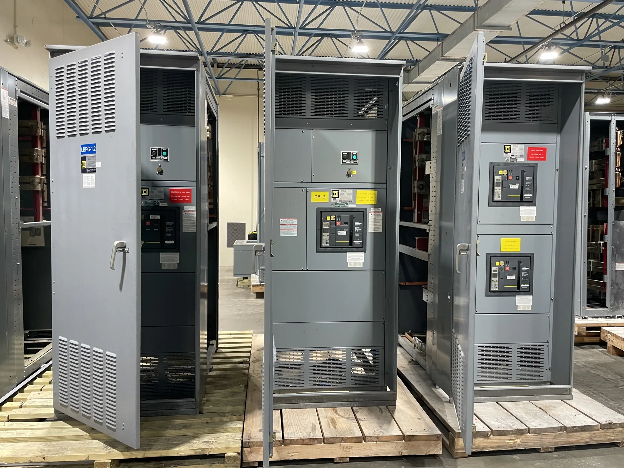
Low-voltage switchgear may be one interface in a facility distribution design, but it is not automatically required for every project. If specified, confirm its voltage class, arrangement, incoming and outgoing connections, protective-device details, and integration with adjacent equipment. A switchboard and switchgear are not interchangeable terms for every design. Applicable listing, ratings, testing, and standards must be checked against the specific assembly and project specification.
For a new-equipment request, provide the latest one-line diagram, equipment schedule, system voltage and source information, specified fault-current data, protective-device requirements, and relevant operating modes. Include enclosure and environmental conditions, cable or bus interface details, control or metering needs, and required submittals when applicable. Flag unresolved assumptions rather than treating them as settled; the responsible engineer and suppliers can identify what must be confirmed before configuration.
Review checklist and purchasing handoff
Before soliciting equipment, align the owner’s continuity priorities with the engineer’s coordination scope. Check that diagrams identify the devices under review, alternate operating arrangements are described, and device data and assumptions are traceable. Specify the required coordination range and deliverables, identify who approves substitutions, and describe how later facility changes trigger technical review. Confirm the project’s applicable standards and any assembly-specific listing expectations with the responsible design team.
Then coordinate the purchasing package with the equipment supplier: identify the exact equipment scope, interfaces, required drawings, review milestones, and procurement schedule. Request clarification where the specification leaves device selection or operating conditions open. A clear handoff helps keep design intent, equipment configuration, and change-control records aligned. Final coordination conclusions remain dependent on the complete system data and engineering review, so document decisions and assumptions before equipment is released for manufacture.