Plan across the facility, not just one panel
Warehouses and logistics facilities can combine service equipment, distribution switchboards, long feeder runs, conveyors, dock equipment, lighting, charging areas and automation. Grounding and bonding should be coordinated across this system rather than treated as a detail confined to one enclosure. The project engineer establishes the electrical design; equipment suppliers need the resulting requirements to configure new distribution equipment appropriately.
Consider a facility expected to add conveyors, vehicle charging or automated material handling in phases. The electrical plan should distinguish installed loads from future assumptions and identify where new feeders or distribution sections may connect. That helps the owner evaluate capacity and layout without presuming that a future addition can be served safely or suitably by any particular piece of equipment.
Clarify the service and grounding arrangement
Grounding and bonding details depend on the system design and service arrangement. The responsible engineer should define the applicable system configuration, the treatment of grounded conductors and equipment grounding paths, and where neutral-to-ground connections belong. Those decisions must be consistent throughout the design. A switchboard drawing or supplier proposal should reflect the approved arrangement, not substitute for the engineer's system-level decisions.
For each distribution point, coordinate the incoming service or feeder, outgoing circuits, grounding provisions, neutral requirements and any specified enclosure or bus details. Confirm which information is part of the equipment scope and which belongs to site-installed conductors, raceways or grounding-electrode work. Clear boundaries help prevent gaps between the equipment package, electrical contractor and field design.
Make feeder growth assumptions explicit
Scalable feeder planning begins with a load schedule, anticipated operating patterns and a description of future phases. Conveyors may operate in groups or under changing duty conditions; charging demand may depend on vehicle quantity, charging strategy and schedules. The engineer should establish the assumptions used for demand and feeder design. A supplier can then review the specified equipment arrangement, spaces and connection requirements without inventing a future load profile.
Expansion provisions involve tradeoffs. Additional sections, feeder positions or reserved physical space may support later work, but they do not automatically establish electrical capacity, fault-duty suitability or compatibility with future equipment. Ask the engineer to identify what is designed now, what is reserved, and what must be reassessed before a later phase. Confirm how future changes could affect the grounding and bonding details and the distribution lineup.
Coordinate charging and automation interfaces
Charging areas and automation introduce interfaces that should be defined before equipment is ordered. The project team should identify intended charging equipment, its supply requirements as established by the design, relevant operating assumptions and proposed distribution locations. For conveyors or automated systems, provide the anticipated feeder destinations and any documented equipment interface requirements. Do not assume that separate loads share the same grounding or neutral treatment; the engineer must determine that from the system design.
Staged construction also calls for a clear work boundary. Show which equipment and feeders are included in the initial phase, which are future provisions, and how later work will be reviewed. Qualified personnel must perform installation, testing and maintenance under applicable safety procedures. Drawings and procurement documents should make it possible for the field team to distinguish approved present connections from planned, unbuilt additions.
Use switchboards as a defined interface
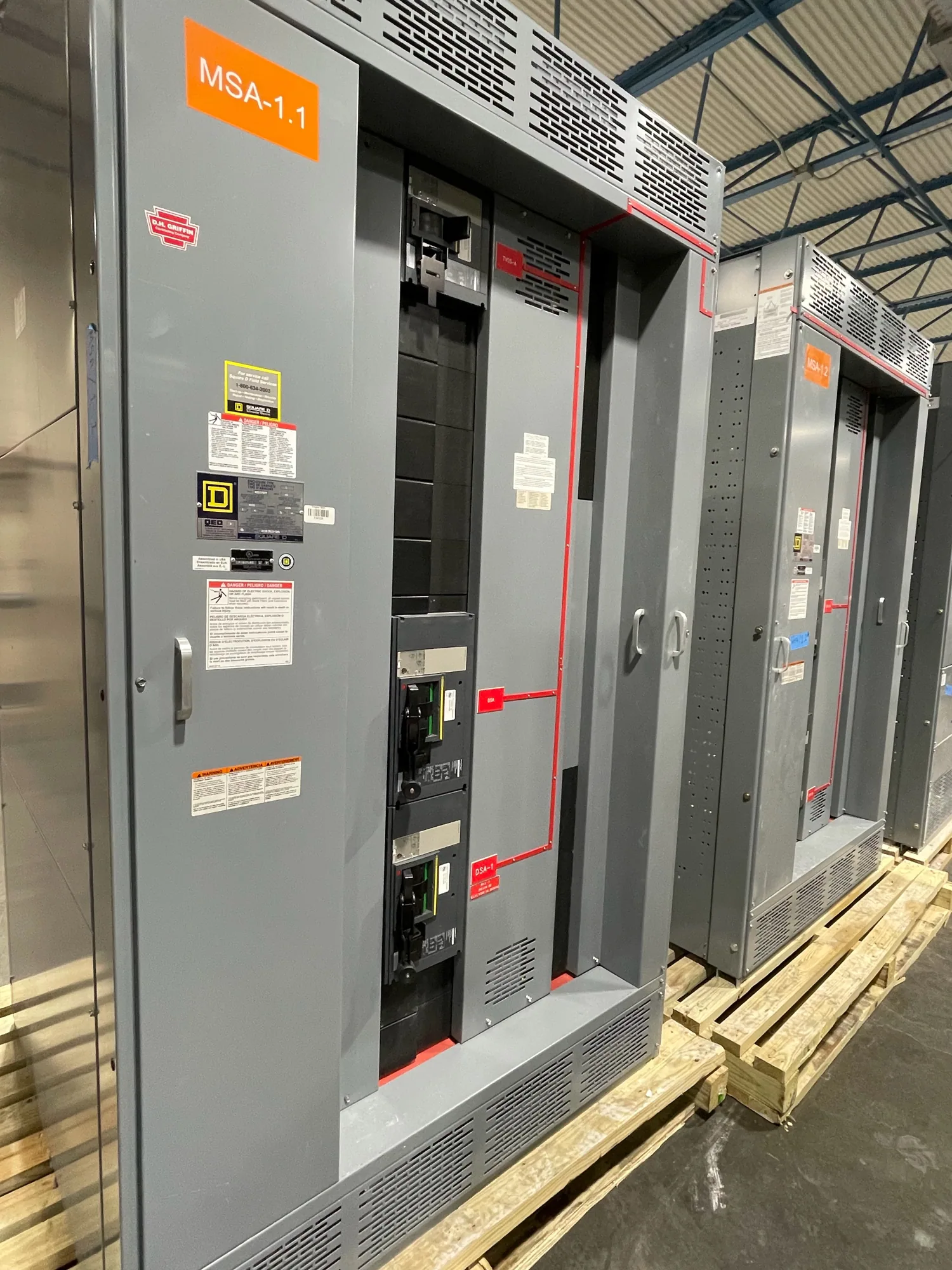
Electrical switchboards are one possible distribution interface, not a universal requirement for every warehouse. When a project specifies a new switchboard, provide the supplier with the engineer-approved one-line diagram, schedules, system and grounding requirements, feeder details, physical constraints and any specified ratings or standards. The supplier should confirm that the proposed configuration matches the actual specification; applicability of any assembly listing or standard must be checked for that design.
Ask the supplier to identify assumptions, exclusions and items requiring engineering confirmation. Compare the proposal with the latest project documents, particularly after changes to charging plans, automation loads or construction phases. Resolve discrepancies before release for manufacture. This coordination reduces the chance that procurement documents describe a different neutral, grounding or feeder arrangement from the one the responsible engineer intended.
Prepare a project-specific information package
Before requesting a quotation, assemble the facility one-line diagram, load and feeder schedules, service information, grounding and bonding notes, equipment locations, environmental conditions and applicable project standards. Mark known future phases separately from current scope. Include the requested equipment type and configuration, connection points, enclosure needs and any delivery constraints. If information is preliminary, label it clearly so open design questions are not mistaken for confirmed requirements.
- Ask the engineer to document the system and neutral-grounding arrangement.
- Identify current loads, charging assumptions and likely expansion stages.
- Show feeder destinations, grounding requirements and equipment-scope boundaries.
- List requested ratings, standards and any project-specific verification needed.
- Assign owner, engineer, contractor and supplier review responsibilities.
Keep procurement aligned through each phase
Grounding and bonding are part of a coordinated electrical design, not a standalone product feature. The owner supplies operational plans; the engineer defines the system; the contractor coordinates field installation; and the manufacturer works from the approved equipment specification. Establish who reviews revisions and how changes to loads, locations or phases are communicated before equipment details are finalized.
South Carolina Switchgear Builders manufactures new switchboards and switchgear to specification, with US-built equipment, all-American components and nationwide shipping. Availability and lead times depend on the order and must be confirmed. Provide the current project documents and identify unresolved assumptions so the equipment review can focus on the facility's actual distribution and grounding requirements.