Scope across treatment and pumping systems
Water and wastewater facilities combine electrical equipment with process systems that may span treatment buildings, pump stations, outdoor installations and remote control points. Grounding and bonding therefore call for a coordinated design, not a detail selected in isolation for one switchgear lineup. The responsible engineer should define how the service, distribution equipment, motors, controls, structures and grounding-electrode system relate to one another.
Each site has its own service arrangement, operating requirements and physical environment. A new switchboard or switchgear assembly must be specified in the context of that system. This discussion supports planning and purchasing; it does not replace project engineering, applicable codes, manufacturer documentation or review by qualified professionals.
Establish the electrical system arrangement
Before requesting equipment, identify the source and distribution arrangement that the design is intended to serve. Provide the nominal voltage and phase, available fault-current information where established, service and feeder details, and the intended equipment location. The engineer should clarify the neutral arrangement and where the system grounding connection is made, as applicable to the actual system. Suppliers need these decisions to evaluate an assembly without guessing at essential interfaces.
Neutral treatment is not interchangeable across every system. The project engineer should specify whether a neutral is present, how it is grounded, and which conductors and bonding points are required at each relevant part of the system. Avoid asking an equipment supplier to infer the grounding method from a facility name or a one-line diagram that leaves key details unresolved. Document the design assumptions and obtain review before releasing the equipment specification.
Coordinate motor loads and starting
Pumps, blowers and other motor-driven loads can affect distribution equipment selection and system behavior during starting and operation. Provide motor schedules, starting methods, drive information and the sequence in which major loads may operate. The engineer can use these details to assess the distribution design and identify the equipment interfaces that need to be specified. Grounding and bonding remain part of the overall design; they do not by themselves resolve voltage drop, starting performance or protection coordination.
Where variable-frequency drives or other electronic controls are involved, identify their locations and the intended connections among the drive, motor, control system and equipment grounding conductors. The responsible designer should determine applicable conductor, bonding and shielding details for the project. Separating power and control requirements in the documents can help suppliers distinguish what belongs to the assembly from what is furnished or installed elsewhere.
Address exposure and installation conditions
Corrosion exposure should be treated as a site-specific concern, not presumed at every facility. Tell the design team about outdoor placement, washdown, chemicals, moisture, coastal exposure or other known conditions that could influence materials, enclosures and bonding interfaces. The project specification should identify the environmental assumptions and request confirmation that the proposed equipment configuration is suitable for the actual location. Availability of a particular construction or finish must be confirmed for the specified design.
Also document mounting, access, conduit or cable entry, grounding connections and the interface with the building or site grounding system. Remote installations may require coordination among electrical, civil, instrumentation and control disciplines. The responsible parties should determine how field-installed conductors and connections are handled, and include clear boundaries between factory-furnished equipment and site work. Installation and testing belong to qualified personnel following applicable safety procedures.
Consider equipment interfaces, not assumptions
Metal-enclosed switchgear may be an option for a project when its electrical characteristics and application fit the design, but the term does not establish that it is required. The engineer should select the equipment type and voltage class from the system requirements, then define grounding and bonding interfaces for the specific assembly. Switchgear, switchboards, motor-control equipment and field devices have distinct functions and specifications; do not treat their names as interchangeable.
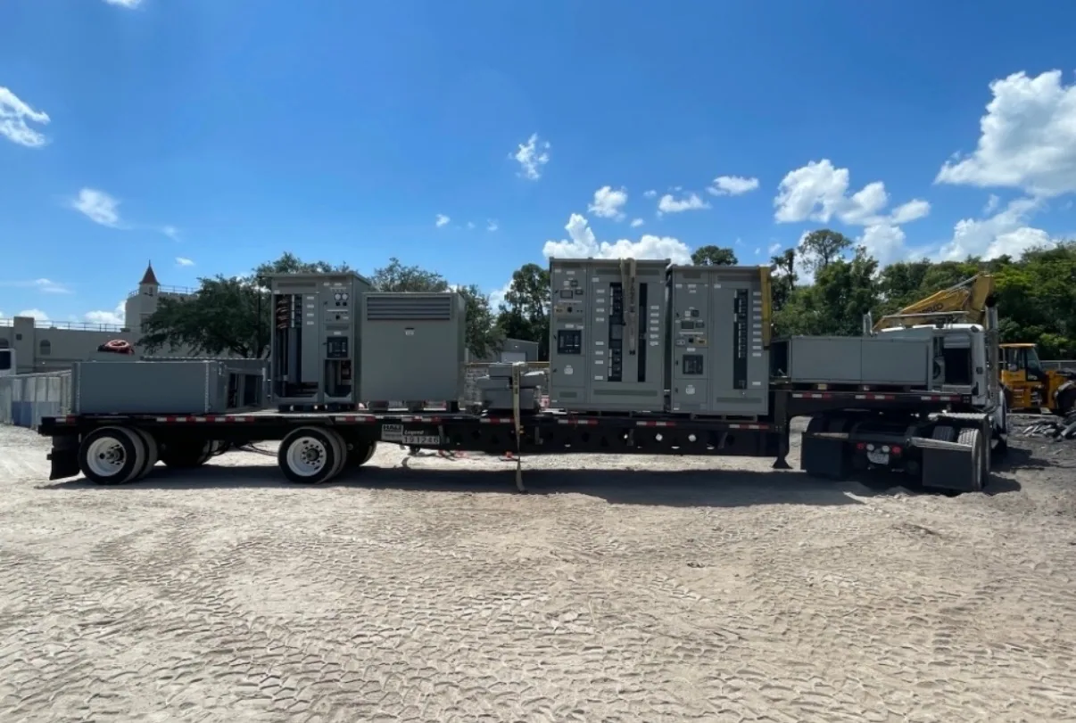
For a new-equipment quotation, send the one-line diagram, equipment schedule, load information, project specifications, site conditions and requested scope. Identify drawings or requirements that are preliminary, and list open questions rather than embedding unverified assumptions. South Carolina Switchgear Builders manufactures new equipment to specification, is US-built with all-American components, and ships nationwide. Configuration, applicable listing, availability and delivery timing depend on the order and require confirmation.
Use a coordinated project checklist
Before procurement, confirm that the owner, electrical engineer, operations team and equipment supplier have reviewed the same design basis. The package should state the service arrangement, voltage, neutral and grounding approach, motor and drive data, control interfaces, environmental conditions, equipment location, required accessories and scope boundaries. Identify applicable codes and standards for the project, and have the responsible engineer determine their applicability to the design and supplied assembly.
Ask the supplier to identify unresolved inputs and confirm the proposed equipment interfaces against the issued specification before production. Review drawings for grounding provisions, neutral details, field connections, access and coordination with connected equipment. Record approved changes so the purchasing documents and final design remain aligned. A well-defined request does not replace engineering judgment; it gives the project team a practical basis for checking fit, resolving questions and procuring new equipment that supports the facility’s documented system design.