Start with the facility and its operating needs
Water and wastewater facilities often combine pumping, treatment processes, building services, and supervisory controls. A relay plan should begin with the electrical system and operating scenarios, not a product feature list. Map the relevant sources, buses, feeders, transformers, and motor circuits, then identify which loads are essential, how they are started, and what operators need to know when a protective device acts.
Conditions vary across a facility. A pump station may have different operating and environmental needs from indoor treatment equipment or an outdoor installation. Document equipment locations, exposure to moisture or corrosive agents where present, access limitations, and the consequences of an outage. These details help the responsible engineer define the application and determine whether protection, enclosure, or control requirements differ by location.
Define protection functions from the system study
Protective functions should follow a project-specific engineering analysis. Depending on the circuit and design, considerations may include overcurrent, ground-fault, voltage, frequency, or motor-related protection. The required functions, thresholds, delays, and trip logic cannot be selected safely from a generic industry list: they depend on the one-line diagram, available fault information, equipment characteristics, operating practices, and coordination with upstream and downstream devices.
Motor starting deserves particular attention. Starting current and duration, acceleration behavior, starting method, and frequency of starts can affect relay settings and the choice of sensing and protection. The engineer should compare expected starting conditions with motor and conductor data and the facility's operating requirements. A setting intended to avoid nuisance trips must still provide the protection established by the engineering study and applicable device documentation.
Match sensing, control power, and interfaces
Specify what each relay must measure and how those measurements will be obtained. Depending on the design, inputs may come from current transformers, voltage transformers, or other approved sensing arrangements. Confirm ratios, accuracy needs, polarity and connection details, and the circuits each device monitors. Missing or inconsistent input information can complicate relay selection, wiring design, commissioning, and later review of event records.
Control power and trip or close circuits also need deliberate definition. Identify the source and acceptable characteristics of control power, required outputs, interlocks, alarms, and breaker or contactor interfaces. If relays exchange status or measurements with a supervisory system, document the required communications, points, protocols, and failure behavior for engineering review. Do not assume a particular relay, communications feature, or control scheme is compatible until the project requirements and manufacturer documentation are checked.
Coordinate settings across equipment and operations
Relay settings are part of a coordinated protection scheme, not an isolated purchase choice. The responsible engineer should establish the study basis, review device curves and available fault data, and assess selectivity alongside motor starting and process continuity. Confirm how a trip should affect related pumps, treatment equipment, standby sources, and alarms. The preferred response may differ by process and must be defined by the owner and project team.
Operators and controls personnel can identify practical requirements that a one-line diagram may not show: which alarms need remote indication, what restart behavior is acceptable, and what information helps diagnose an interruption. Bring these stakeholders into review before the equipment design is finalized. Where equipment may face corrosive exposure, specify the actual location and conditions for evaluation rather than assuming a particular material, coating, or enclosure rating is adequate.
Understand the equipment boundary
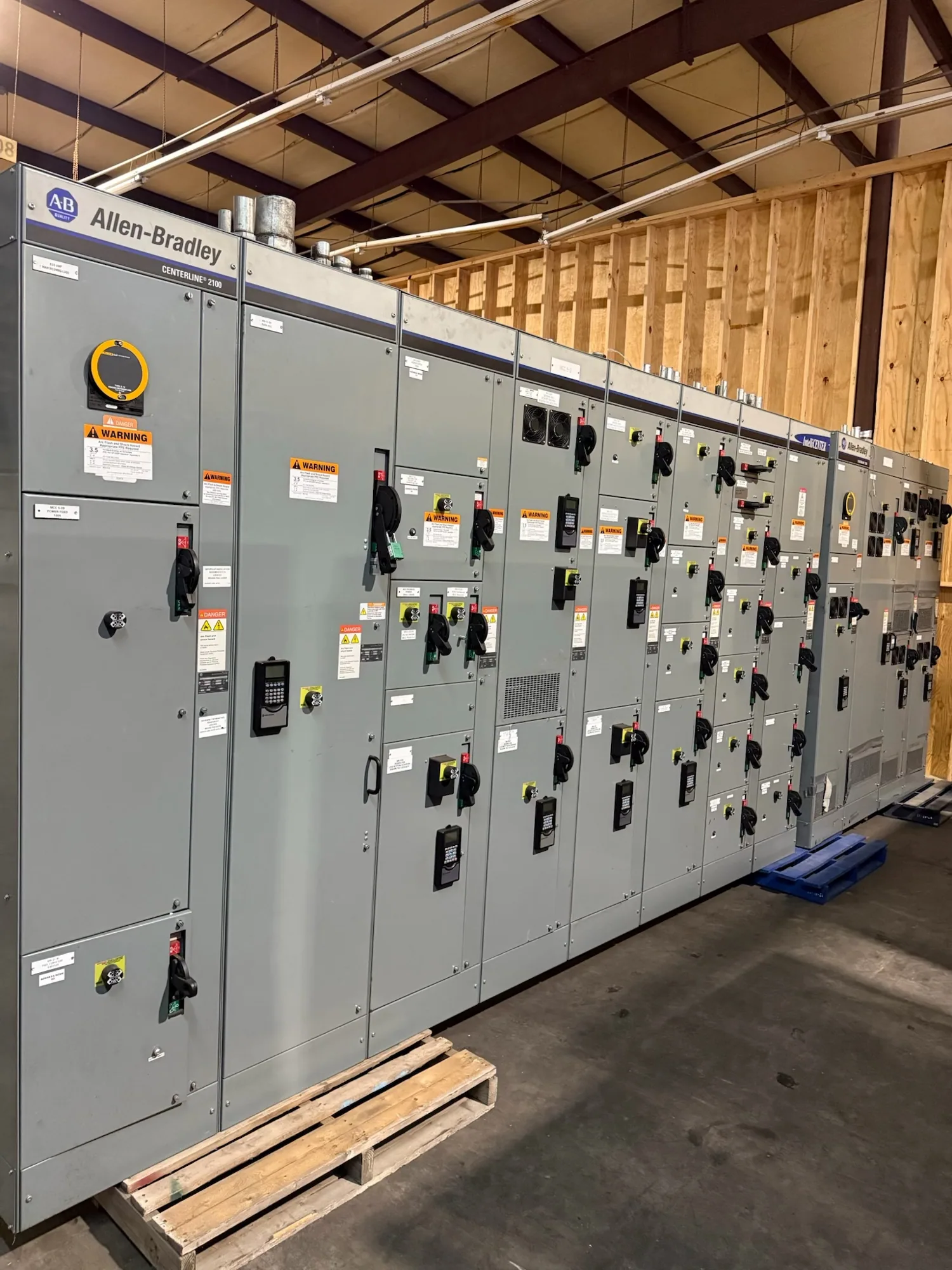
Relay requirements may apply within switchgear, a switchboard, motor-control equipment, or another part of the distribution system. Low-voltage switchgear can serve as an illustrative interface when the project design calls for it, but it is not automatically required for every water or wastewater facility. The engineer should identify equipment boundaries, protective devices, instrument connections, and responsibility for supplying and configuring each component.
When requesting new equipment, provide the latest one-line diagram, load and motor schedules, available fault information, protection study criteria, and control schematics when available. Include specified relay functions, sensing details, control power, communications, environmental conditions, and required documentation. Identify unresolved assumptions clearly. A manufacturer can evaluate a proposed configuration against the supplied specification; project-specific ratings, availability, delivery timing, testing, listing, and standards applicability require confirmation for the actual design.
Use a project checklist before requesting a quotation
Gather owner and engineer decisions on the system arrangement, motor starting, protection objectives, coordination basis, and operating priorities. Record relevant ambient and corrosion conditions, installation location, control-system interfaces, and any required alarms or event data. Ask the engineer to identify applicable standards and governing project documents, and to resolve conflicts or open technical questions before they become purchasing assumptions.
Then confirm equipment scope, relay and sensing responsibilities, drawings, settings deliverables, review points, and the parties responsible for installation and commissioning. Qualified personnel must perform installation, testing, and maintenance under applicable safety procedures; equipment procurement does not replace engineering or field verification. With a complete, reviewed specification, South Carolina Switchgear Builders can assess a new-equipment request and coordinate the proposed build to the project's defined requirements.