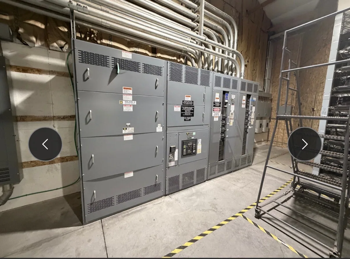
Start with the facility’s electrical system — Short-Circuit Ratings for Water and Wastewater Facilities
Water and wastewater facilities often bring together intake and lift-station pumps, treatment processes, aeration, chemical feed, building services, controls and communications. Their electrical distribution may span multiple buildings or outdoor locations, with different transformers, feeders and operating conditions. Short-circuit ratings should therefore be considered throughout the system, not selected from a single equipment label or a broad facility description.
The core comparison is between the fault current available at an equipment location and the equipment’s applicable interrupting and short-circuit withstand capabilities. The responsible electrical engineer determines the available fault current using project-specific system information and evaluates how protective devices and assemblies are applied. A rating that appears adequate at one bus may not resolve requirements at another point downstream or across a separate source.
Establish available fault current by location
Useful starting information includes utility or upstream source data, transformer characteristics, conductor sizes and lengths, generator or other alternate-source details, and the proposed distribution arrangement. The engineer uses verified inputs to calculate or establish available fault current at relevant buses and equipment terminals. Where inputs are preliminary, identify assumptions and mark them for confirmation rather than treating early estimates as final design values.
Facilities may have normal and alternate operating configurations, such as a standby generator, tie breaker, or multiple sources. Those arrangements can change which equipment is energized and the fault current that may be available under a given condition. Ask the project engineer to define the configurations that must be evaluated and the protective-device coordination approach. Suppliers need the approved design basis, not an assumed single-source scenario.
Distinguish equipment ratings and protection
Interrupting capacity and assembly withstand ratings address related but distinct parts of the design. A protective device must be suitable for the fault current it is required to interrupt under its specified application. The assembly also needs an applicable short-circuit current rating or withstand capability for the design and protective arrangement. Confirm the exact rating terminology and basis in the equipment specification; do not assume one number automatically establishes every component or system requirement.
For low-voltage switchboards, UL 891 may apply to eligible designs, but applicability and any assembly listing must be verified for the specific configuration. Do not transfer that standard to medium-voltage switchgear. The engineer should state the required voltage class, equipment type, fault-current basis, protective-device information, and applicable standards for each assembly. Ratings, testing, and listing depend on the actual design and supplied equipment and require confirmation.
Account for motors and operating duty
Large motors are central to many water and wastewater processes. Starting method, motor size, operating sequence, and the number of motors running together can affect voltage performance and protective-device coordination. These considerations inform system design, but motor starting conditions should not be substituted for a short-circuit study. Provide the engineer with motor schedules, starter or drive details, duty requirements, and anticipated operating modes so the fault-current and coordination analyses reflect the intended facility.
Variable-frequency drives, soft starters, control power, alarms, and communications also influence equipment interfaces and panel layouts. Specify which functions belong in the switchgear, switchboard, or separate control equipment, and identify required signals and interlocks. Avoid assuming that a power assembly includes a particular control scheme. Clear responsibility boundaries help the engineer and manufacturer confirm the design without confusing protective functions, process control, and equipment monitoring.
Consider the installation environment
Corrosion exposure varies by site and location. Outdoor installations, humid process areas, chemical handling zones, and washdown conditions may call for different enclosure materials, finishes, environmental protection, or placement. Describe actual exposure and installation conditions rather than relying on a general “water plant” label. The engineer should define applicable environmental requirements, while the equipment supplier confirms which construction options are available for the specified assembly.
Also identify access, working clearances, cable entry direction, conduit locations, room dimensions, and whether equipment is indoors or outdoors. These details affect lineup arrangement, maintainability, and coordination with civil and electrical work. Qualified personnel must perform installation, testing, and maintenance under applicable safety procedures. Project documents should establish safe work planning and the responsible parties rather than implying that equipment selection alone resolves site safety.
Prepare a coordinated equipment specification
Before requesting a proposal for new equipment, assemble one consistent package: one-line diagrams, load and motor schedules, voltage class, available fault-current study or stated design basis, protective-device requirements, source configurations, control interfaces, environmental conditions, and dimensional constraints. Include the required standards and submittal expectations, while flagging items that remain subject to engineering review. This lets suppliers identify design questions instead of filling gaps with unapproved assumptions.
Owners, consulting engineers, electrical contractors, operations staff, and equipment suppliers each contribute different information. Confirm who approves ratings and protection, who owns control integration, and who coordinates utility or generator data. South Carolina Switchgear Builders manufactures new switchgear and switchboards to specification, with US-built equipment, all-American components, and nationwide shipping. Availability and lead times depend on the order and must be confirmed; final configuration and ratings require review against the project specification.
Review before release and procurement
Use the final review to reconcile calculations, drawings, equipment schedules, and procurement documents. Check that each assembly’s specified rating corresponds to its location and the evaluated system configuration; verify protective-device details, voltage class, environmental construction, and control boundaries. Resolve discrepancies before approval, especially where a revised transformer, generator, feeder, or tie arrangement could alter the engineering basis.
For a complete request, provide the current design documents, identify open decisions, and name the stakeholders responsible for approval. The manufacturer can then review the requested new-equipment configuration against the supplied specification and confirm project-specific availability, ratings, listing status where applicable, and delivery details. This sequence keeps short-circuit selection tied to the engineered system and supports a more coordinated purchasing and installation plan.