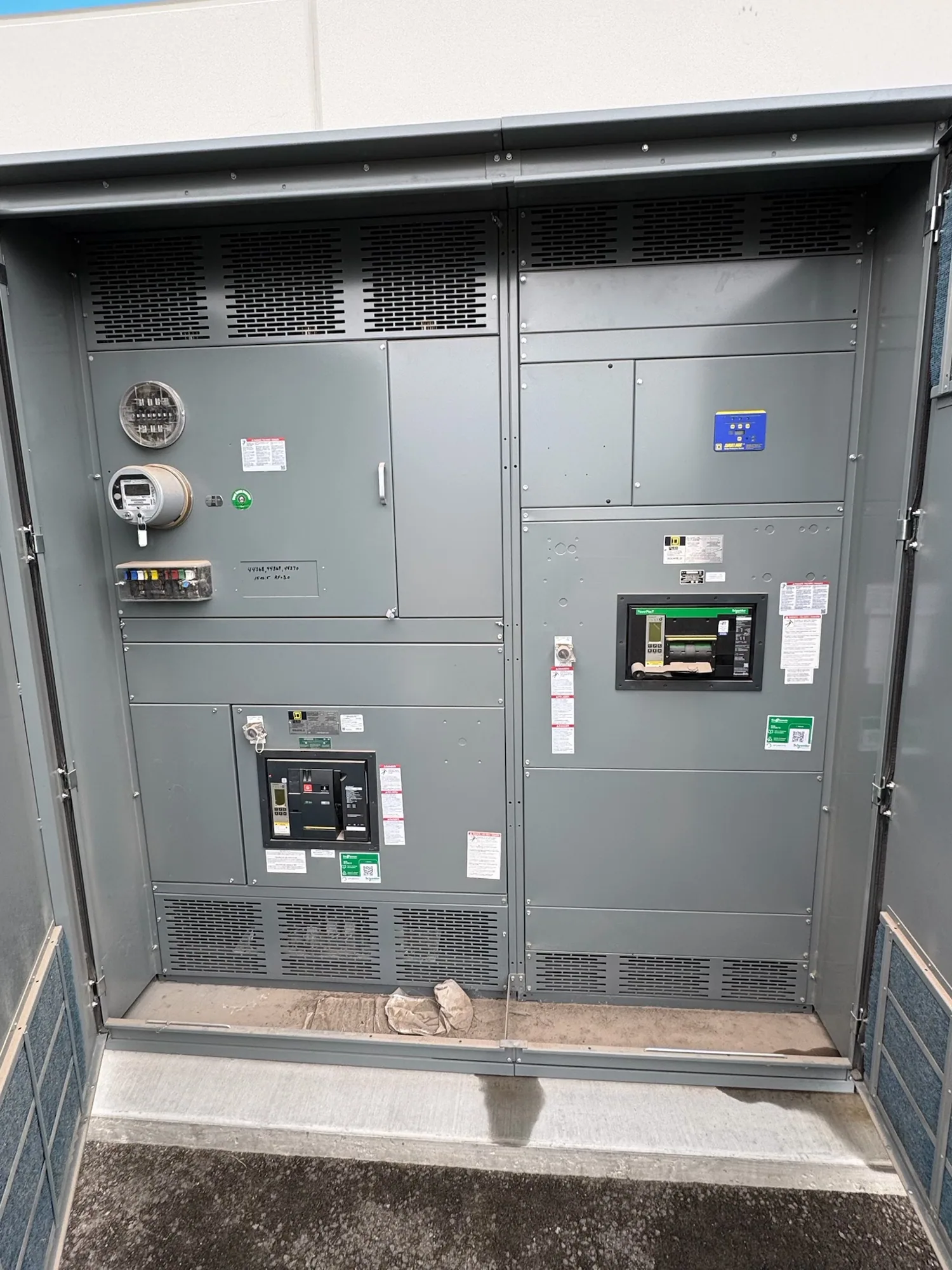
Selection starts with the complete assembly
Switchgear component selection is not simply a matter of choosing individual devices from a catalog. Breakers, switches, protective relays, control devices, bus, and enclosure features must work together in the equipment design. A component that fits one requirement may affect space, connections, protection, maintenance access, or the ratings of the completed assembly.
Begin with the project’s one-line diagram, equipment schedule, and design criteria. Identify the equipment type and voltage class, incoming and outgoing circuits, source arrangement, load requirements, and the functions expected of each section. The responsible engineer should resolve design assumptions and confirm which requirements are mandatory before components are specified for manufacture.
Choose switching and protection devices by function
For each circuit, document what the device must do: carry normal load, interrupt specified fault current, isolate equipment, or provide a particular protective function. Breakers and switches are not interchangeable just because their physical forms appear similar. The circuit application, operating sequence, control scheme, and specified device ratings all matter; the final selection needs to be compatible with the intended assembly.
Protective relays and trip functions also depend on the system design. Confirm which conditions must be detected, what equipment or circuits the protection should affect, and how control power and status signals are provided. Where settings, coordination, or relay logic are design-dependent, the project engineer should define and review them. Component selection alone does not establish that a protection scheme is coordinated or suitable.
Check fault-current and assembly requirements
Available fault current at the equipment location is a key input. Compare the project’s fault-current information with the applicable interrupting ratings of switching devices and the short-circuit withstand or current ratings specified for the assembled equipment. These are related but distinct checks: a device rating does not, by itself, prove that the complete assembly meets the project requirement.
Provide the source and system information used for the fault-current study, including any assumptions that affect the result. Ask the responsible engineer to confirm the required ratings and their basis, and have the equipment design reviewed against them. Do not select a component using a general rule of thumb where the system calculation, configuration, or specified assembly rating is still uncertain.
Coordinate buses, controls, and physical fit
Bus configuration and connections must suit the specified current path, section arrangement, and equipment design. Confirm phase arrangement, neutral or grounding requirements where applicable, connection locations, and how incoming and outgoing conductors interface with the assembly. The design team should also review enclosure dimensions, cable entry, access, and site constraints so that component placement remains practical for installation and later work by qualified personnel.
Control components require the same care. List control voltage, interlocks, indication, metering, communications, and external input or output points that the design calls for. Identify which signals originate in the switchgear and which depend on owner systems, contractors, or separately supplied equipment. Make interface responsibilities explicit rather than assuming that a component choice automatically resolves wiring, programming, or system integration.
Confirm what belongs to the manufacturer and others
In a manufacturing process, the equipment design and assembly must support the specified components as a coordinated whole. Component availability and compatibility are subject to confirmation for the actual design. Distinguish manufacturer-supplied equipment from devices, wiring, protective studies, field connections, and other work assigned to the owner, engineer, or contractor. This boundary is especially important when project documents refer to equipment or systems outside the switchgear assembly.
Review proposed substitutions through the project’s approval process. A substitute may differ in dimensions, terminal arrangement, operating characteristics, control interface, or documentation. Ask whether a change affects the one-line diagram, equipment schedule, ratings, coordination study, or other approved design documents. Any revision should be evaluated by the responsible parties and incorporated consistently before manufacturing proceeds.
Prepare a useful component-selection package
For a clear technical review, provide the latest one-line diagram, equipment schedule, applicable specifications, fault-current information, and project-specific control requirements. Include the equipment location and interface constraints, requested device functions, and any owner standards that affect configuration. Mark unresolved items as open questions; an explicit assumption is easier to review than a requirement left implicit.
Review submittal information for alignment among component descriptions, drawings, ratings, control diagrams, and the stated scope. Confirm who approves technical deviations and who supplies external signals or connections. A concise, coordinated package helps identify mismatches early and gives the manufacturer a sound basis to evaluate the equipment design against the project requirements.
Use a deliberate handoff to the next stage
Before selection is finalized, check that every circuit has a defined function, device requirements are documented, fault-current and assembly-rating criteria are available, and controls and interfaces have assigned owners. Verify that project drawings and specifications agree, and record decisions that affect configuration. If information is pending, identify who will resolve it and when it is needed for the design review.
Once the requirements are sufficiently clear, component selection can feed into detailed assembly design and submittal review. The project team should resolve open technical questions before approving changes or authorizing the equipment configuration. This disciplined handoff keeps component choices tied to the specified complete assembly, while leaving installation, testing, and maintenance to qualified personnel following applicable project and safety procedures.