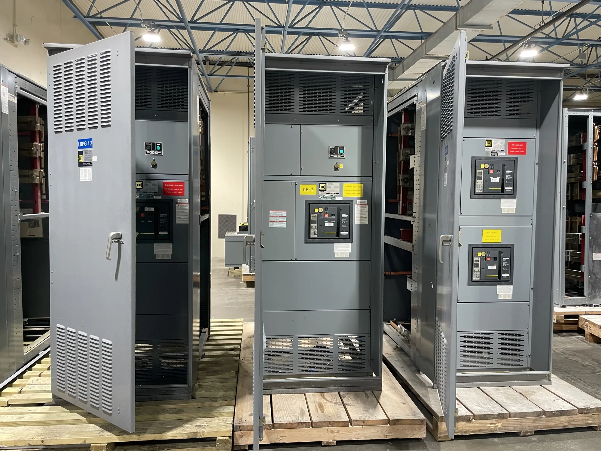
Busbars are part of an engineered assembly
Busbars provide conductive paths within switchgear, connecting incoming power, bus sections and outgoing circuits as defined by the equipment design. Their fabrication is not an isolated metalworking task: conductor shape, connections, supports, insulation and clearances must work together in the intended assembly. For a new-equipment project, the key question is how the busbar design will be manufactured and verified as part of the specified switchgear.
South Carolina Switchgear Builders manufactures new equipment to project specifications. A buyer evaluating busbar manufacturing should establish whether the supplier is responsible for the complete assembly, specified bus fabrication within that assembly, or a separately defined scope. Confirming those boundaries early helps avoid gaps between engineering, fabrication, assembly and inspection responsibilities.
Define the electrical and mechanical requirements
Start with the equipment type and project application, then provide the approved one-line diagram and applicable equipment specifications. Identify the specified voltage class, continuous current requirements, available fault-duty information, system arrangement and any requirements for main, tie or distribution bus. The responsible project engineer must determine which design criteria apply; a voltage or current value by itself does not define a complete busbar design.
Conductor material and geometry affect more than procurement. Copper or aluminum, conductor arrangement, surface treatment and connection details may influence conductivity, mechanical handling, joint design and space within the enclosure. These choices should be evaluated for the specific assembly, rather than treated as interchangeable options. Provide any material restrictions or project preferences, and ask the manufacturer to identify assumptions that require engineering approval.
Joints, preparation and contact surfaces
Every bus joint is an important interface. Joint design may specify mating surfaces, hardware, preparation, contact treatment and assembly method. The approved design should make clear which components are supplied, who prepares the conductors, who completes the joint, and what inspection or documentation is required. Do not assume that a drawing showing a connection also defines every fabrication and assembly step.
Joint quality depends on following the applicable design and assembly instructions. Requirements for fasteners, tightening, surface condition and verification must be established for the particular equipment; they should not be replaced with generic values. When a project has special joint materials, coatings or inspection expectations, submit them with the inquiry. The supplier and responsible engineer can then resolve compatibility and responsibility before production proceeds.
Supports, insulation and fault-duty coordination
Supports hold conductors in their intended position and contribute to the mechanical behavior of the bus system. Their location and construction must align with the assembly design, including clearances, barriers and access for connections. Under fault conditions, forces can act on conductors and supports; therefore, the specified fault duty and design evidence must be considered together. Do not infer suitability from conductor size or visual appearance alone.
Insulation and spacing are likewise coordinated features, not finish details selected in isolation. The project documents should identify any required insulation system, barriers or environmental considerations and the equipment conditions those requirements address. Temperature performance, fault-duty capability and applicable design evidence depend on the particular configuration. Ask what documentation is available for the proposed assembly and confirm that it matches the final approved design.
Fabrication scope and inspection boundaries
Clarify who cuts, forms, drills, deburrs, finishes and identifies each bus conductor, and whether these operations are included in the equipment supplier’s scope. Also define who installs supports and insulation, makes electrical joints, performs inspections and records results. If another contractor supplies or modifies part of the bus system, establish the interface and approval process before treating the assembly as complete.
Inspection plans should reflect the project specification and the manufacturer’s documented process. Buyers can ask which fabrication features are checked, how deviations are handled, and what records accompany the equipment. Testing and listing are configuration-specific matters: request confirmation against the actual proposed assembly rather than assuming that a general capability statement applies to every design.
Information to provide for a useful review
A clear inquiry can include the one-line diagram, equipment arrangement, bus material preference, current and fault-duty requirements, voltage class, connection points, enclosure constraints and relevant project specifications. Add the required delivery location, target schedule and any inspection or documentation expectations. If some values remain under engineering review, label them as preliminary so they are not mistaken for approved design inputs.
Ask the manufacturer to identify open questions, exclusions and assumptions in its response. Confirm which party approves the bus design, resolves interface conflicts and authorizes changes after approval. For custom-to-specification new equipment, this coordination helps keep conductor fabrication aligned with the complete assembly rather than a standalone drawing or material list.
Coordinate busbar decisions before release
Before production, review the approved drawings and scope for material, joints, supports, insulation, ratings, inspection and responsibility boundaries. Verify that any design evidence or listing requirements apply to the actual equipment configuration, and confirm the order-specific availability and delivery schedule. South Carolina Switchgear Builders builds new switchgear and switchboards in the United States and ships nationwide; configuration and timing depend on the confirmed project requirements.
When requesting a quotation, provide the best available engineering package and identify decisions still awaiting approval. A focused review can establish what busbar fabrication is included, what information is needed to complete the design, and how the bus system will be coordinated with the new assembly. Qualified personnel must handle installation, testing and maintenance under applicable safety procedures.