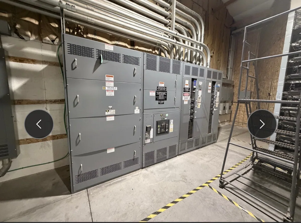
Define what the retrofit must accomplish
A switchgear retrofit project replaces some or all of an existing lineup with newly manufactured equipment. The first decision is the project boundary: identify which sections, protective devices, metering, controls and connected circuits are included, and which remain in service. That scope shapes the equipment design, demolition plan, temporary operating arrangements and coordination needed among the owner, engineer, manufacturer and installation contractor.
Replacement may be driven by equipment condition, capacity needs, a facility change or difficulty supporting an older installation. Those motivations do not establish what the new assembly can fit or accomplish. The responsible engineer should define electrical requirements and operating priorities, then confirm the proposed configuration against the existing system and site. A clear scope also helps distinguish manufacturer-supplied equipment from field engineering, removal, installation and commissioning work.
Survey existing conditions before design
Retrofit drawings can be incomplete or out of date. Before equipment is specified, gather the current one-line diagram, available wiring and control diagrams, equipment nameplate information, photographs and dimensional records. A qualified project team should verify critical field conditions, including lineup location, access route, ceiling or overhead obstructions, floor and anchorage details, cable entry points, bus connections and clearances needed for operation and maintenance.
Physical fit requires more than matching the old lineup’s overall width. Confirm section arrangement, depth, height, door swing, working space, conduit or cable paths, and how the new equipment will reach its final position. Existing foundations, enclosures and adjacent equipment may constrain the layout. Where drawings and field measurements disagree, identify the discrepancy early and assign someone to resolve it; a new assembly should not be assumed to fit based on a legacy outline alone.
Resolve electrical and control interfaces
Provide the project engineer with the system voltage, available fault information, source and load arrangement, grounding approach, protection requirements and any operating sequences that affect the lineup. Confirm the required device functions, ratings and compartment arrangement from project documents rather than relying on assumptions about the existing equipment. For a 480 V class application, specify the low-voltage equipment requirements; other voltage classes require equipment selected for that class.
Interfaces extend beyond power conductors. Document control power sources, trip and close circuits, interlocks, remote indications, communications, metering and alarm points that must be retained or changed. Identify wire and terminal conventions where they matter, along with external connections and control-system responsibilities. The engineer and manufacturer should review the available information together and record unresolved items as design questions, not as presumed compatibility with legacy devices or wiring.
Balance fit, replacement scope and future needs
A closely matched replacement can reduce changes to the surrounding room and connected systems, but preserving every existing interface may constrain layout or future flexibility. A broader redesign may provide a cleaner arrangement or accommodate revised loads, yet can require more engineering, cable work, space and outage coordination. Compare these paths using documented site conditions and lifecycle needs; neither a minimal change nor a full replacement is automatically the better choice.
Decide whether the project replaces an entire lineup or only a defined portion, and ask how boundaries affect bus continuity, protection coordination, access and future expansion. Any retained equipment, transition sections or adapters must be evaluated for the specific design by the responsible engineer. Confirm applicable ratings, listing and standards for the actual assembly. UL 891 may apply to eligible low-voltage switchboards, but applicability and assembly listing must be verified; it is not a general designation for all switchgear.
Plan outages and field responsibilities
Equipment supply is only one part of a retrofit. The owner and project team should establish the outage window, shutdown sequence, load transfer strategy and any temporary arrangements before setting a cutover plan. The installation contractor typically coordinates field measurements, demolition, rigging, anchorage, conductor termination and site work within the agreed contract scope. Assign responsibility for each interface so that equipment design assumptions match the actual installation plan.
Clarify who will develop and approve field connections, verify protection settings, perform installation inspections and conduct commissioning tests. Those activities require qualified personnel following applicable safety procedures; do not plan work on energized equipment as a shortcut. Identify who will manage permits, access, lifting constraints, waste handling and coordination with facility operations. Delivery dates and equipment availability depend on the confirmed specification and order, so align procurement milestones with the project schedule rather than assuming a standard turnaround.
Prepare a useful equipment request
A focused request helps the manufacturer evaluate the new equipment scope. Include the one-line diagram, equipment schedules, existing nameplate details, verified dimensions, photographs, system and fault data, control requirements, cable entry information, room constraints and the planned cutover window. Mark which documents are current, note known discrepancies, and distinguish firm requirements from items still under engineering review.
- Define the equipment sections and functions to be replaced, and identify any retained interfaces.
- Provide electrical requirements and the engineer’s available fault and protection information.
- Share verified dimensions, access constraints, cable routes and connection details.
- State the outage assumptions, target milestones and installation contractor’s scope.
- List open questions about drawings, ratings, controls, listing or applicable standards.
Coordinate the path from specification to cutover
South Carolina Switchgear Builders manufactures new equipment to specification, with US-built equipment, all-American components and nationwide shipping. Confirm configuration, availability and actual lead time against the project requirements; delivery dates are order-dependent. Before release, review drawings and interface points with the responsible engineer and field contractor, then document approved revisions and remaining responsibilities.
For a sound retrofit plan, treat verified site information, electrical design and installation coordination as a single sequence. The owner defines operating priorities, the engineer establishes system requirements, the manufacturer develops equipment to the approved specification, and qualified field personnel execute the installation and testing plan. Resolving questions before fabrication and scheduling cutover around the confirmed scope makes the transition to new equipment more deliberate and manageable.