Define the equipment’s role in the distribution system
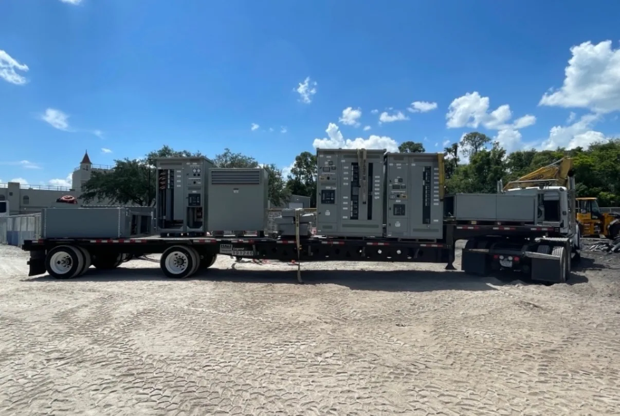
Pad-mounted switchgear is considered when distribution equipment must interface with underground conductors and be installed at grade on a prepared foundation. Its role may involve sectionalizing feeders, providing switching points, or serving a defined part of a site distribution system. The exact function depends on the one-line diagram and operating plan; the enclosure’s appearance alone does not establish how the assembly is configured.
Start by identifying the system voltage class, source and load connections, number of feeders, and what operators need to isolate or switch. Confirm whether the equipment is part of a customer-owned system, a utility interface, or both. These distinctions affect responsibility for design review, protection coordination, operating procedures, and approval. Do not assume a manufacturer’s standard arrangement satisfies a utility’s requirements.
Coordinate underground cable interfaces
Underground cable entry is a central design constraint. The project team should establish conductor type and size, termination approach, cable quantity, phase arrangement, and entry direction. The equipment layout must provide usable space for cable terminations and bending without conflict with the foundation, conduits, adjacent equipment, or access areas. The responsible engineer and cable installer should confirm the needed dimensions from actual cable data.
Show conduit locations and stub-up details on the site and foundation drawings, and coordinate them with the proposed compartment layout before concrete work. Confirm whether cable routes approach from below, from a side, or through another specified interface. Changes made after foundation construction can create costly field conflicts. Any proposed busway or other transition should be treated as a separately engineered interface, with ratings, connection details, and physical clearances verified for the complete arrangement.
Resolve switching and protection requirements
Describe the switching tasks rather than requesting a generic “switchgear” arrangement. Identify which feeders require isolation, whether sectionalizing is needed, and what operating sequence the project expects. The engineer should determine device types and ratings from the system design, including applicable load and fault conditions. Protection, fusing, relaying, and coordination choices are not interchangeable; they need to match the one-line diagram and the responsibilities assigned to each device.
Provide available fault-current information and the source assumptions used to establish it. The responsible electrical engineer must confirm required ratings and protective-device coordination for the actual system. Also clarify whether the project requires provisions for future ways or connections. Spare capacity can influence enclosure dimensions, cable space, and cost, so it is better to specify a defined future provision than leave expansion expectations implicit.
Fit the foundation, access, and enclosure to the site
Review the equipment location against the civil plan, finished grade, drainage, nearby structures, vehicle routes, landscaping, and underground utilities. The foundation must support the specified assembly and align with its entry points; foundation design and anchorage require project-specific coordination. Check that doors and operating areas can be reached and used without obstruction, and preserve the working and maintenance clearances required by the project design and applicable rules.
Describe exposure conditions that could affect enclosure selection, such as precipitation, airborne contaminants, washdown, temperature range, or potential impact. State the required enclosure characteristics in the specification and have them confirmed for the proposed design. Do not infer suitability from the phrase “outdoor rated” alone. Site conditions, materials, coatings, ventilation, and access controls should be evaluated together, especially where equipment is exposed or difficult to reach.
Grounding and utility coordination
Grounding is an engineered system interface, not an accessory detail. Provide the project grounding plan, bonding expectations, and available site information for review by the responsible engineer. Coordinate grounding connections with the foundation, cable shields, enclosure, and system grounding method as applicable. The precise configuration depends on the equipment and electrical system; do not assume that a generic grounding arrangement is appropriate for every installation.
Where a utility connection or approval is involved, obtain the applicable utility requirements directly and include them with the RFQ. Confirm the required drawings, review process, approved connection details, switching responsibilities, and any specified equipment features before design is finalized. Utility acceptance should not be presumed from a product description. The project team must verify that the proposed configuration is acceptable for its service arrangement.
Clarify scope, assumptions, and delivery
Pad-mounted equipment is a site-specific configuration, not a universally interchangeable product. Before ordering, compare the proposed arrangement with the one-line diagram, site plan, cable schedule, foundation details, and utility criteria. Identify what the manufacturer is expected to supply and what remains by others, including civil work, conduits, field terminations, protection settings, installation, and commissioning. Written scope boundaries help prevent gaps between equipment supply and field responsibilities.
South Carolina Switchgear Builders manufactures new switchgear and switchboards to specification, with US-built equipment and all-American components. Configuration, availability, applicable listing, ratings, testing, and delivery timing depend on the specific order and must be confirmed. Short lead times may be available, but actual timing is order-dependent. Nationwide shipping can be coordinated once equipment scope, destination, and project schedule are understood.
Prepare a useful request for quotation
For an informed review, provide the latest one-line diagram, system voltage, feeder count and arrangement, available fault-duty information, switching requirements, and any protection criteria. Include cable and conduit data, the site plan, proposed foundation dimensions, access constraints, and environmental conditions. Attach utility requirements or approval comments when applicable, and identify the requested enclosure features and any future provisions.
Also state the required submittal documents, project milestones, ship-to location, and division of field responsibilities. Flag unresolved assumptions instead of presenting them as settled requirements; the project engineer can identify which items need confirmation before release. With these details, the manufacturer can assess the requested configuration and clarify open interfaces. Final drawings, ratings, listing applicability, and delivery expectations should be reviewed and confirmed for the specific supplied equipment before the order proceeds.