Start with the operating problem, not a catalog choice
For a Greenwood, South Carolina project, the right starting point is the facility’s electrical scope and operating constraints—not an assumption about what equipment a particular site already has. A planned expansion, a capacity change, or replacement work in a constrained electrical room can each call for a different arrangement. Document what must remain in service, what loads are changing, and which decisions belong to the project engineer.
Industrial facilities may have a mix of process loads, building services, and motor-driven equipment. Treat that as a planning scenario to validate against the actual facility. Identify the source and distribution arrangement, intended voltage class, load schedule, and available fault-current information if known. The responsible engineer should confirm system conditions, ratings, applicable requirements, and whether the scope calls for low-voltage switchgear, a switchboard, or another product type.
Plan feeder isolation and maintainable arrangements
Feeder isolation affects how a fault, inspection, or planned change can be managed. Ask which loads need separate feeders, whether process areas should be divided into meaningful sections, and what operating sequence is expected when equipment is isolated. A more segmented arrangement can support selective shutdowns, but it may add equipment, space, connections, and coordination work. The best balance depends on the one-line diagram and operating priorities.
Maintainability also depends on the physical installation. Provide room dimensions, access and working-space constraints for the design team to review, cable-entry preferences, routing limitations, and any environmental conditions specified for the equipment location. Confirm which side or sides need access and how the equipment will be moved into position. These details can affect enclosure arrangement and shipping divisions; they should be settled before a final configuration is approved.
Coordinate protection with the actual system
Protective-device selection is not a standalone equipment choice. The time-current behavior of upstream and downstream devices influences how faults are cleared and which portions of a system may be affected. Selective coordination goals, fault-current values, and project requirements must be assessed for the actual system by the responsible engineer. Do not assume a particular trip setting, device combination, or coordination outcome without a reviewed design.
Include available studies, device schedules, and the latest one-line diagram with the RFQ when they exist. If they are not yet complete, identify what remains open and who will provide it. Ask the manufacturer to confirm which design inputs are needed to configure the specified equipment and what information must be resolved before production. That early exchange can reduce avoidable revisions without substituting equipment documentation for engineering review.
Consider motor control centers where they fit
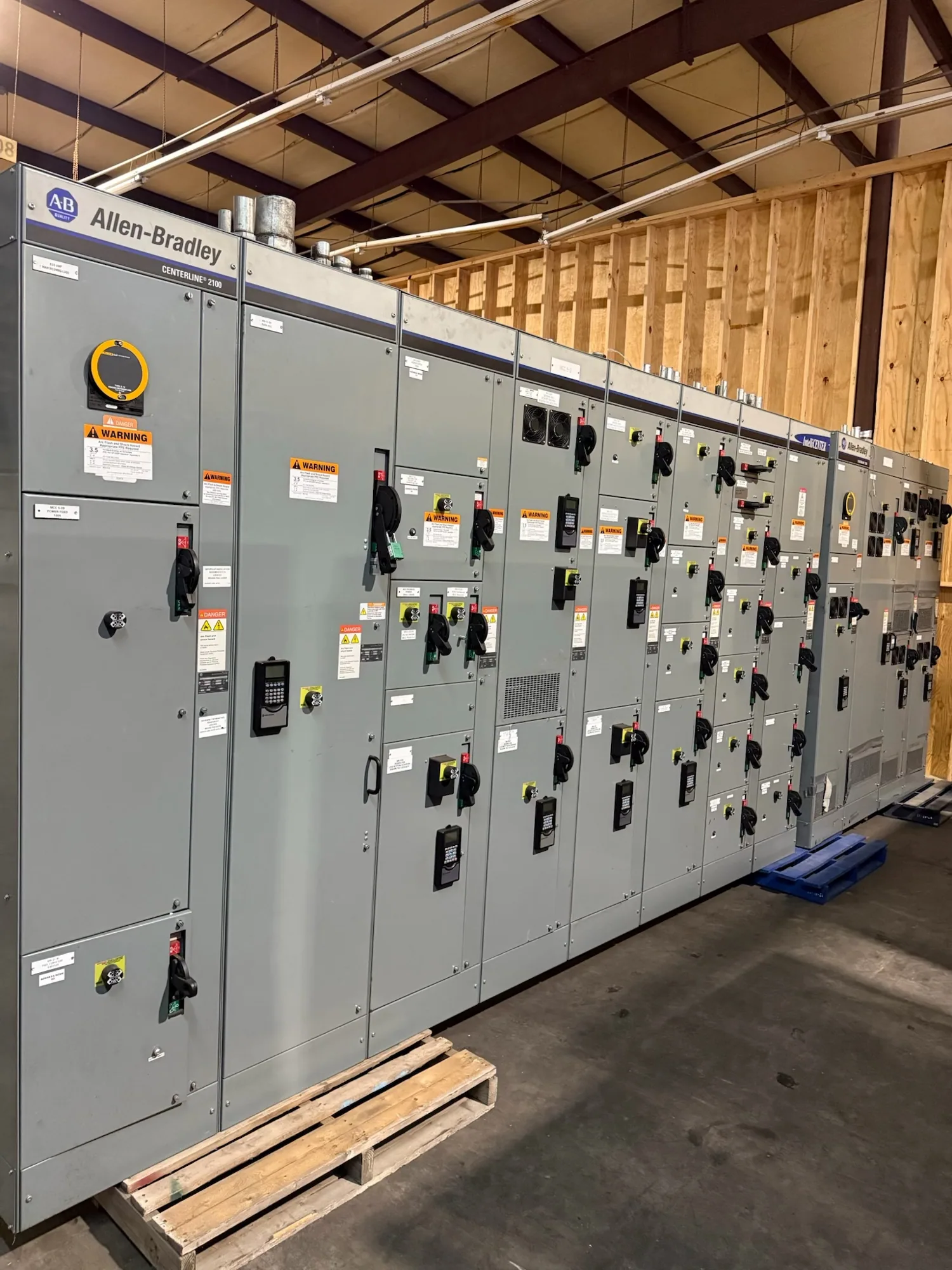
In a hypothetical food and beverage facility project, motor control centers may be worth evaluating when a defined group of motor circuits needs a coordinated, organized distribution approach. The decision depends on the motor list, control functions, starting methods, fault conditions, space, and maintenance practices. An MCC is not automatically the right choice for every motor load, nor does its presence determine the upstream switchgear arrangement.
For comparison, provide motor nameplate or scheduled data, control requirements, expected operating sequences, and any separation or maintainability goals. Clarify which circuits are part of the MCC scope and which remain in other distribution equipment. The project engineer should confirm equipment ratings, protection, and interfaces. A clear boundary between switchgear, switchboards, MCCs, and field-installed controls helps each supplier quote the intended scope.
Sequence upgrades around facility operations
When a project must limit interruptions, define the replacement sequence before selecting an arrangement. Identify the equipment being replaced, temporary operating constraints, shutdown windows, cutover responsibilities, and dependencies on other contractors. Do not assume a new assembly can be installed or energized without site-specific planning. Installation, testing, and maintenance must be performed by qualified personnel using applicable safety procedures.
Replacement planning should also address interfaces: existing cable locations, conduit routes, grounding, control wiring, communications, and connections to upstream or downstream equipment. Record known dimensions and flag anything that needs field verification. If the design requires phased delivery or separate sections, describe the sequence in the RFQ and ask what drawings and approvals are needed to coordinate manufacture and shipment.
Build a useful Greenwood project RFQ
A strong request for quotation identifies the project location, equipment function, voltage class, one-line diagram, load and feeder schedules, required ratings, enclosure and access conditions, and applicable project specifications. Include the desired delivery location and requested schedule, while recognizing that availability and actual lead times depend on the order and must be confirmed. Describe drawing review, documentation, testing, and listing needs as project requirements for confirmation.
South Carolina Switchgear Builders manufactures new equipment to specification, is US-built with all-American components, and ships nationwide. Ask for confirmation that the proposed design matches the project documents, including any requested assembly listing or standards applicability; these are design-dependent and must be verified for the specific equipment. Provide one coordinated package of current documents, name a technical decision-maker, and identify open questions. Clear inputs make it easier to evaluate configuration, resolve interfaces, and plan the next project steps.