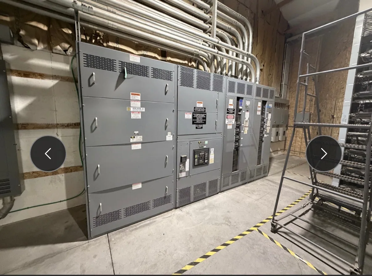
What a 2000 A rating describes
For a specific switchgear assembly, 2000 A denotes a nominal continuous-current rating only when the manufacturer’s documentation identifies that rating for the assembly and its intended conditions. It is not a promise that every load can draw 2000 A without interruption, nor does it establish the rating of each breaker, feeder, or connected component. The complete equipment schedule and nameplate information matter.
Current rating must be considered with system voltage, configuration, installation conditions, and the project’s calculated loads. A rating by itself does not establish short-circuit capability, suitability for a particular environment, or compliance with project requirements. The responsible electrical engineer should determine the required equipment characteristics and verify that the proposed assembly documentation addresses them.
Relate calculated demand to the main bus
Consider a hypothetical project where preliminary calculations lead the engineer to evaluate a 2000 A main bus. That number should follow a documented load assessment, not simply the sum of every connected load at full nameplate current. The engineer determines how applicable demand assumptions, operating schedules, future provisions, and project rules affect the required capacity. Those calculations are project-specific and should not be inferred from the bus label.
Ask whether expected operating conditions leave suitable capacity for the project’s intended operation and planned changes. A design that fits the present load may not suit anticipated additions; conversely, selecting a larger rating without a defined need can affect equipment dimensions, interfaces, and cost. The equipment supplier can build to the approved specification, but the design team must establish the required rating and confirm the basis for it.
Distinguish bus rating from device ratings
A 2000 A main bus does not mean that each outgoing circuit is rated 2000 A. Main protective devices, feeder devices, bus sections, and connection points have their own specified ratings and functions. The one-line diagram and feeder schedule should show how the proposed arrangement serves each load, identifies the main configuration, and coordinates with upstream and downstream equipment.
Confirm that the assembly documentation matches the specified continuous-current rating and configuration, including any relevant sections or transitions. If the project includes multiple sources, ties, or operating modes, the engineer should identify which configurations may carry current and how the equipment is intended to operate. Do not assume that a rating stated for one section or condition automatically applies to every arrangement.
Temperature rise and installation conditions
Current flowing through bus conductors produces heat. How a particular assembly manages that heat depends on its design and the conditions specified for use. Ambient temperature, enclosure arrangement, ventilation, nearby equipment, and installation location may affect the review. Ask the manufacturer to confirm the proposed assembly against the project’s stated conditions rather than treating 2000 A as independent of its environment.
Provide the intended indoor or outdoor setting, enclosure requirements, ambient conditions, and any space or ventilation constraints known to the design team. Also identify cable or busway entry locations and working clearances that may influence the layout. These inputs help resolve practical interfaces early; they do not replace the engineer’s review of applicable electrical codes or the manufacturer’s confirmation of the design.
Fault duty is a separate design question
Continuous-current rating and short-circuit rating describe different requirements. A 2000 A bus rating alone says nothing about the fault current the equipment can withstand or interrupt. The project’s short-circuit study and protective-device information provide the basis for specifying applicable fault-duty requirements. The engineer must confirm that the proposed equipment and devices suit the available fault conditions and system arrangement.
Fault forces can place mechanical demands on bus supports and bracing. This is why the specified fault-duty rating must be evaluated alongside the continuous-current choice, not guessed from the ampere rating. Submit the study results and protective-device details for review, and confirm the relevant ratings against the actual equipment documentation. Do not assume a particular rating or test outcome without project-specific evidence.
Layout, access, and project coordination
A 2000 A assembly’s physical arrangement must work within the electrical room and with connected equipment. Confirm lineup space, access for qualified installation and maintenance, cable bending and termination needs, entry directions, and the locations of upstream and downstream connections. Clearances and work practices must be established by the project team under applicable requirements; a current rating does not determine the room layout.
Resolve these interfaces before the design is finalized. Changes to feeder count, termination approach, source arrangement, or room constraints can affect the equipment configuration. Share the latest one-line diagram, equipment schedule, and layout information with the manufacturer, then review drawings for consistency before release. Actual dimensions, delivery dates, and project-specific equipment details require confirmation against the approved design and order.
Information to provide for a 2000 A review
For a useful equipment review, provide the load schedule and calculation basis, system voltage, one-line diagram, feeder list, short-circuit study, protective-device requirements, environmental conditions, and available room and connection details. Identify any future capacity or operating modes the project requires. The responsible engineer should confirm the rating and applicable code requirements; the manufacturer can then assess the specified new assembly and document the offered configuration.
South Carolina Switchgear Builders manufactures new switchgear to specification, with US-built equipment, all-American components, and nationwide shipping. Availability and lead times depend on the order and must be confirmed. Before procurement, reconcile the approved technical specification, drawings, and equipment documentation so the 2000 A designation is understood in context—not treated as a substitute for load calculations, fault-duty review, or coordinated project design.